Hi Kris
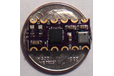
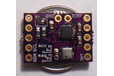
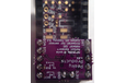
I am running the attached code on a Teensy3.1 and a cheap MPU9250
(http://www.ebay.com/itm/SPI-IIC-MPU-9250-9-Axis-Attitude-Gyro-Accelerator-Magnetometer-Sensor-Module-/131185485892)
I plotted raw data in Matlab and accelerometer,gyro, and magnetometer are all calibrated, The problem is when I Serial.Print (pitch, yaw, roll) after a certain angle they become unstable and they interfere with each other. I am using madwick algorithm as you can see in my code.
Would you please let me know what is wrong with it?
Thanks
Navid
Here is my Code:
/* MPU9250 Basic Example Code
by: Kris Winer
date: April 1, 2014
license: Beerware - Use this code however you'd like. If you
find it useful you can buy me a beer some time.
Demonstrate basic MPU-9250 functionality including parameterizing the register addresses, initializing the sensor,
getting properly scaled accelerometer, gyroscope, and magnetometer data out. Added display functions to
allow display to on breadboard monitor. Addition of 9 DoF sensor fusion using open source Madgwick and
Mahony filter algorithms. Sketch runs on the 3.3 V 8 MHz Pro Mini and the Teensy 3.1.
SDA and SCL should have external pull-up resistors (to 3.3V).
10k resistors are on the EMSENSR-9250 breakout board.
Hardware setup:
MPU9250 Breakout --------- Arduino
VDD ---------------------- 3.3V
VDDI --------------------- 3.3V
SDA ----------------------- A4
SCL ----------------------- A5
GND ---------------------- GND
Note: The MPU9250 is an I2C sensor and uses the Arduino Wire library.
Because the sensor is not 5V tolerant, we are using a 3.3 V 8 MHz Pro Mini or a 3.3 V Teensy 3.1.
We have disabled the internal pull-ups used by the Wire library in the Wire.h/twi.c utility file.
We are also using the 400 kHz fast I2C mode by setting the TWI_FREQ to 400000L /twi.h utility file.
*/
include <SPI.h>
include <Wire.h>
// See also MPU-9250 Register Map and Descriptions, Revision 4.0, RM-MPU-9250A-00, Rev. 1.4, 9/9/2013 for registers not listed in
// above document; the MPU9250 and MPU9150 are virtually identical but the latter has a different register map
//
//Magnetometer Registers
define AK8963_ADDRESS 0x0C
define WHO_AM_I_AK8963 0x00 // should return 0x48
define INFO 0x01
define AK8963_ST1 0x02 // data ready status bit 0
define AK8963_XOUT_L 0x03 // data
define AK8963_XOUT_H 0x04
define AK8963_YOUT_L 0x05
define AK8963_YOUT_H 0x06
define AK8963_ZOUT_L 0x07
define AK8963_ZOUT_H 0x08
define AK8963_ST2 0x09 // Data overflow bit 3 and data read error status bit 2
define AK8963_CNTL 0x0A // Power down (0000), single-measurement (0001), self-test (1000) and Fuse ROM (1111) modes on bits 3:0
define AK8963_ASTC 0x0C // Self test control
define AK8963_I2CDIS 0x0F // I2C disable
define AK8963_ASAX 0x10 // Fuse ROM x-axis sensitivity adjustment value
define AK8963_ASAY 0x11 // Fuse ROM y-axis sensitivity adjustment value
define AK8963_ASAZ 0x12 // Fuse ROM z-axis sensitivity adjustment value
define SELF_TEST_X_GYRO 0x00
define SELF_TEST_Y_GYRO 0x01
define SELF_TEST_Z_GYRO 0x02
/*#define X_FINE_GAIN 0x03 // [7:0] fine gain
define Y_FINE_GAIN 0x04
define Z_FINE_GAIN 0x05
define XA_OFFSET_H 0x06 // User-defined trim values for accelerometer
define XA_OFFSET_L_TC 0x07
define YA_OFFSET_H 0x08
define YA_OFFSET_L_TC 0x09
define ZA_OFFSET_H 0x0A
define ZA_OFFSET_L_TC 0x0B */
define SELF_TEST_X_ACCEL 0x0D
define SELF_TEST_Y_ACCEL 0x0E
define SELF_TEST_Z_ACCEL 0x0F
define SELF_TEST_A 0x10
define XG_OFFSET_H 0x13 // User-defined trim values for gyroscope
define XG_OFFSET_L 0x14
define YG_OFFSET_H 0x15
define YG_OFFSET_L 0x16
define ZG_OFFSET_H 0x17
define ZG_OFFSET_L 0x18
define SMPLRT_DIV 0x19
define CONFIG 0x1A
define GYRO_CONFIG 0x1B
define ACCEL_CONFIG 0x1C
define ACCEL_CONFIG2 0x1D
define LP_ACCEL_ODR 0x1E
define WOM_THR 0x1F
define MOT_DUR 0x20 // Duration counter threshold for motion interrupt generation, 1 kHz rate, LSB = 1 ms
define ZMOT_THR 0x21 // Zero-motion detection threshold bits [7:0]
define ZRMOT_DUR 0x22 // Duration counter threshold for zero motion interrupt generation, 16 Hz rate, LSB = 64 ms
define FIFO_EN 0x23
define I2C_MST_CTRL 0x24
define I2C_SLV0_ADDR 0x25
define I2C_SLV0_REG 0x26
define I2C_SLV0_CTRL 0x27
define I2C_SLV1_ADDR 0x28
define I2C_SLV1_REG 0x29
define I2C_SLV1_CTRL 0x2A
define I2C_SLV2_ADDR 0x2B
define I2C_SLV2_REG 0x2C
define I2C_SLV2_CTRL 0x2D
define I2C_SLV3_ADDR 0x2E
define I2C_SLV3_REG 0x2F
define I2C_SLV3_CTRL 0x30
define I2C_SLV4_ADDR 0x31
define I2C_SLV4_REG 0x32
define I2C_SLV4_DO 0x33
define I2C_SLV4_CTRL 0x34
define I2C_SLV4_DI 0x35
define I2C_MST_STATUS 0x36
define INT_PIN_CFG 0x37
define INT_ENABLE 0x38
define DMP_INT_STATUS 0x39 // Check DMP interrupt
define INT_STATUS 0x3A
define ACCEL_XOUT_H 0x3B
define ACCEL_XOUT_L 0x3C
define ACCEL_YOUT_H 0x3D
define ACCEL_YOUT_L 0x3E
define ACCEL_ZOUT_H 0x3F
define ACCEL_ZOUT_L 0x40
define TEMP_OUT_H 0x41
define TEMP_OUT_L 0x42
define GYRO_XOUT_H 0x43
define GYRO_XOUT_L 0x44
define GYRO_YOUT_H 0x45
define GYRO_YOUT_L 0x46
define GYRO_ZOUT_H 0x47
define GYRO_ZOUT_L 0x48
define EXT_SENS_DATA_00 0x49
define EXT_SENS_DATA_01 0x4A
define EXT_SENS_DATA_02 0x4B
define EXT_SENS_DATA_03 0x4C
define EXT_SENS_DATA_04 0x4D
define EXT_SENS_DATA_05 0x4E
define EXT_SENS_DATA_06 0x4F
define EXT_SENS_DATA_07 0x50
define EXT_SENS_DATA_08 0x51
define EXT_SENS_DATA_09 0x52
define EXT_SENS_DATA_10 0x53
define EXT_SENS_DATA_11 0x54
define EXT_SENS_DATA_12 0x55
define EXT_SENS_DATA_13 0x56
define EXT_SENS_DATA_14 0x57
define EXT_SENS_DATA_15 0x58
define EXT_SENS_DATA_16 0x59
define EXT_SENS_DATA_17 0x5A
define EXT_SENS_DATA_18 0x5B
define EXT_SENS_DATA_19 0x5C
define EXT_SENS_DATA_20 0x5D
define EXT_SENS_DATA_21 0x5E
define EXT_SENS_DATA_22 0x5F
define EXT_SENS_DATA_23 0x60
define MOT_DETECT_STATUS 0x61
define I2C_SLV0_DO 0x63
define I2C_SLV1_DO 0x64
define I2C_SLV2_DO 0x65
define I2C_SLV3_DO 0x66
define I2C_MST_DELAY_CTRL 0x67
define SIGNAL_PATH_RESET 0x68
define MOT_DETECT_CTRL 0x69
define USER_CTRL 0x6A // Bit 7 enable DMP, bit 3 reset DMP
define PWR_MGMT_1 0x6B // Device defaults to the SLEEP mode
define PWR_MGMT_2 0x6C
define DMP_BANK 0x6D // Activates a specific bank in the DMP
define DMP_RW_PNT 0x6E // Set read/write pointer to a specific start address in specified DMP bank
define DMP_REG 0x6F // Register in DMP from which to read or to which to write
define DMP_REG_1 0x70
define DMP_REG_2 0x71
define FIFO_COUNTH 0x72
define FIFO_COUNTL 0x73
define FIFO_R_W 0x74
define WHO_AM_I_MPU9250 0x75 // Should return 0x71
define XA_OFFSET_H 0x77
define XA_OFFSET_L 0x78
define YA_OFFSET_H 0x7A
define YA_OFFSET_L 0x7B
define ZA_OFFSET_H 0x7D
define ZA_OFFSET_L 0x7E
// Using the MSENSR-9250 breakout board, ADO is set to 0
// Seven-bit device address is 110100 for ADO = 0 and 110101 for ADO = 1
define ADO 1
if ADO
define MPU9250_ADDRESS 0x68 // Device address when ADO = 1
else
define MPU9250_ADDRESS 0x69 // Device address when ADO = 0
define AK8963_ADDRESS 0x0C // Address of magnetometer
endif
define AHRS true // set to false for basic data read
define SerialDebug true // set to true to get Serial output for debugging
// Set initial input parameters
enum Ascale {
AFS_2G = 0,
AFS_4G,
AFS_8G,
AFS_16G
};
enum Gscale {
GFS_250DPS = 0,
GFS_500DPS,
GFS_1000DPS,
GFS_2000DPS
};
enum Mscale {
MFS_14BITS = 0, // 0.6 mG per LSB
MFS_16BITS // 0.15 mG per LSB
};
// Specify sensor full scale
uint8_t Gscale = GFS_250DPS;
uint8_t Ascale = AFS_2G;
uint8_t Mscale = MFS_16BITS; // Choose either 14-bit or 16-bit magnetometer resolution
uint8_t Mmode = 0x02; // 2 for 8 Hz, 6 for 100 Hz continuous magnetometer data read
float aRes, gRes, mRes; // scale resolutions per LSB for the sensors
// Pin definitions
int intPin = 12; // These can be changed, 2 and 3 are the Arduinos ext int pins
int myLed = 13; // Set up pin 13 led for toggling
int16_t accelCount[3]; // Stores the 16-bit signed accelerometer sensor output
int16_t gyroCount[3]; // Stores the 16-bit signed gyro sensor output
int16_t magCount[3]; // Stores the 16-bit signed magnetometer sensor output
float magCalibration[3] = {0, 0, 0}, magbias[3] = {0, 0, 0}; // Factory mag calibration and mag bias
float gyroBias[3] = {0, 0, 0}, accelBias[3] = {0, 0, 0}; // Bias corrections for gyro and accelerometer
int16_t tempCount; // temperature raw count output
float temperature; // Stores the real internal chip temperature in degrees Celsius
float SelfTest[6]; // holds results of gyro and accelerometer self test
// global constants for 9 DoF fusion and AHRS (Attitude and Heading Reference System)
float GyroMeasError = PI * (40.0f / 180.0f); // gyroscope measurement error in rads/s (start at 40 deg/s)
float GyroMeasDrift = PI * (0.0f / 180.0f); // gyroscope measurement drift in rad/s/s (start at 0.0 deg/s/s)
// There is a tradeoff in the beta parameter between accuracy and response speed.
// In the original Madgwick study, beta of 0.041 (corresponding to GyroMeasError of 2.7 degrees/s) was found to give optimal accuracy.
// However, with this value, the LSM9SD0 response time is about 10 seconds to a stable initial quaternion.
// Subsequent changes also require a longish lag time to a stable output, not fast enough for a quadcopter or robot car!
// By increasing beta (GyroMeasError) by about a factor of fifteen, the response time constant is reduced to ~2 sec
// I haven't noticed any reduction in solution accuracy. This is essentially the I coefficient in a PID control sense;
// the bigger the feedback coefficient, the faster the solution converges, usually at the expense of accuracy.
// In any case, this is the free parameter in the Madgwick filtering and fusion scheme.
float beta = sqrt(3.0f / 4.0f) * GyroMeasError; // compute beta
float zeta = sqrt(3.0f / 4.0f) * GyroMeasDrift; // compute zeta, the other free parameter in the Madgwick scheme usually set to a small or zero value
define Kp 2.0f * 5.0f // these are the free parameters in the Mahony filter and fusion scheme, Kp for proportional feedback, Ki for integral
define Ki 0.0f
uint32_t delt_t = 0; // used to control display output rate
uint32_t count = 0, sumCount = 0; // used to control display output rate
float pitch, yaw, roll;
float deltat = 0.0f, sum = 0.0f; // integration interval for both filter schemes
uint32_t lastUpdate = 0, firstUpdate = 0; // used to calculate integration interval
uint32_t Now = 0; // used to calculate integration interval
float ax, ay, az, gx, gy, gz, mx, my, mz; // variables to hold latest sensor data values
float q[4] = {1.0f, 0.0f, 0.0f, 0.0f}; // vector to hold quaternion
float eInt[3] = {0.0f, 0.0f, 0.0f}; // vector to hold integral error for Mahony method
void setup()
{
Wire.begin();
// TWBR = 12; // 400 kbit/sec I2C speed
Serial.begin(115200);
// Set up the interrupt pin, its set as active high, push-pull
pinMode(intPin, INPUT);
digitalWrite(intPin, LOW);
pinMode(myLed, OUTPUT);
digitalWrite(myLed, HIGH);
delay(1000);
// Read the WHO_AM_I register, this is a good test of communication
byte c = readByte(MPU9250_ADDRESS, WHO_AM_I_MPU9250); // Read WHO_AM_I register for MPU-9250
delay(1000);
if (c == 0x71) // WHO_AM_I should always be 0x68
{
MPU9250SelfTest(SelfTest); // Start by performing self test and reporting values
calibrateMPU9250(gyroBias, accelBias); // Calibrate gyro and accelerometers, load biases in bias registers
delay(1000);
initMPU9250();
// Serial.println("MPU9250 initialized for active data mode...."); // Initialize device for active mode read of acclerometer, gyroscope, and temperature
// Read the WHO_AM_I register of the magnetometer, this is a good test of communication
byte d = readByte(AK8963_ADDRESS, WHO_AM_I_AK8963); // Read WHO_AM_I register for AK8963
delay(1000);
// Get magnetometer calibration from AK8963 ROM
initAK8963(magCalibration); //Serial.println("AK8963 initialized for active data mode...."); // Initialize device for active mode read of magnetometer
delay(1000);
}
else
{
// Serial.print("Could not connect to MPU9250: 0x");
// Serial.println(c, HEX);
while(1) ; // Loop forever if communication doesn't happen
}
}
void loop()
{
// If intPin goes high, all data registers have new data
if (readByte(MPU9250_ADDRESS, INT_STATUS) & 0x01) { // On interrupt, check if data ready interrupt
readAccelData(accelCount); // Read the x/y/z adc values
getAres();
// Now we'll calculate the accleration value into actual g's
ax = (float)accelCount[0]*aRes; // - accelBias[0]; // get actual g value, this depends on scale being set
ay = (float)accelCount[1]*aRes; // - accelBias[1];
az = (float)accelCount[2]*aRes; // - accelBias[2];
readGyroData(gyroCount); // Read the x/y/z adc values
getGres();
// Calculate the gyro value into actual degrees per second
gx = (float)gyroCount[0]*gRes; // get actual gyro value, this depends on scale being set
gy = (float)gyroCount[1]*gRes;
gz = (float)gyroCount[2]*gRes;
readMagData(magCount); // Read the x/y/z adc values
getMres();
magbias[0] = +281.; // User environmental x-axis correction in milliGauss, should be automatically calculated
magbias[1] = +231.; // User environmental x-axis correction in milliGauss
magbias[2] = -406.; // User environmental x-axis correction in milliGauss
// Calculate the magnetometer values in milliGauss
// Include factory calibration per data sheet and user environmental corrections
mx = (float)magCount[0]*mRes*magCalibration[0] - magbias[0]; // get actual magnetometer value, this depends on scale being set
my = (float)magCount[1]*mRes*magCalibration[1] - magbias[1];
mz = (float)magCount[2]*mRes*magCalibration[2] - magbias[2];
ax=ax-850/1000;
ay=ay-850/1000;
az=az+500/1000;
}
Now = micros();
deltat = ((Now - lastUpdate)/1000000.0f); // set integration time by time elapsed since last filter update
lastUpdate = Now;
sum += deltat; // sum for averaging filter update rate
sumCount++;
// Sensors x (y)-axis of the accelerometer is aligned with the y (x)-axis of the magnetometer;
// the magnetometer z-axis (+ down) is opposite to z-axis (+ up) of accelerometer and gyro!
// We have to make some allowance for this orientationmismatch in feeding the output to the quaternion filter.
// For the MPU-9250, we have chosen a magnetic rotation that keeps the sensor forward along the x-axis just like
// in the LSM9DS0 sensor. This rotation can be modified to allow any convenient orientation convention.
// This is ok by aircraft orientation standards!
// Pass gyro rate as rad/s
MadgwickQuaternionUpdate(ax, ay, az, gx_PI/180.0f, gy_PI/180.0f, gz_PI/180.0f, my, mx, mz);
//MahonyQuaternionUpdate(ax, ay, az, gx_PI/180.0f, gy_PI/180.0f, gz_PI/180.0f, my, mx, mz);
// Serial print and/or display at 0.5 s rate independent of data rates
delt_t = millis() - count;
if (delt_t > 50) { // update LCD once per half-second independent of read rate
if(SerialDebug) {
// Define output variables from updated quaternion---these are Tait-Bryan angles, commonly used in aircraft orientation.
// In this coordinate system, the positive z-axis is down toward Earth.
// Yaw is the angle between Sensor x-axis and Earth magnetic North (or true North if corrected for local declination, looking down on the sensor positive yaw is counterclockwise.
// Pitch is angle between sensor x-axis and Earth ground plane, toward the Earth is positive, up toward the sky is negative.
// Roll is angle between sensor y-axis and Earth ground plane, y-axis up is positive roll.
// These arise from the definition of the homogeneous rotation matrix constructed from quaternions.
// Tait-Bryan angles as well as Euler angles are non-commutative; that is, the get the correct orientation the rotations must be
// applied in the correct order which for this configuration is yaw, pitch, and then roll.
// For more see http://en.wikipedia.org/wiki/Conversion_between_quaternions_and_Euler_angles which has additional links.
yaw = atan2(2.0f * (q[1] * q[2] + q[0] * q[3]), q[0] * q[0] + q[1] * q[1] - q[2] * q[2] - q[3] * q[3]);
pitch = -asin(2.0f * (q[1] * q[3] - q[0] * q[2]));
roll = atan2(2.0f * (q[0] * q[1] + q[2] * q[3]), q[0] * q[0] - q[1] * q[1] - q[2] * q[2] + q[3] * q[3]);
pitch *= 180.0f / PI;
yaw *= 180.0f / PI;
//yaw -= 13.8; // Declination at Danville, California is 13 degrees 48 minutes and 47 seconds on 2014-04-04
roll *= 180.0f / PI;
if(SerialDebug) {
//Serial.print("Yaw, Pitch, Roll: ");
int sensorvalue = analogRead (A2);
Serial.print(sensorvalue);
Serial.print("\t");
Serial.print(yaw, 2);
Serial.print("\t");
Serial.print(pitch, 2);
Serial.print("\t");
Serial.println(roll, 2);
//Serial.print("rate = "); Serial.print((float)sumCount/sum, 2); Serial.println(" Hz");
}
// With these settings the filter is updating at a ~145 Hz rate using the Madgwick scheme and
// >200 Hz using the Mahony scheme even though the display refreshes at only 2 Hz.
// The filter update rate is determined mostly by the mathematical steps in the respective algorithms,
// the processor speed (8 MHz for the 3.3V Pro Mini), and the magnetometer ODR:
// an ODR of 10 Hz for the magnetometer produce the above rates, maximum magnetometer ODR of 100 Hz produces
// filter update rates of 36 - 145 and ~38 Hz for the Madgwick and Mahony schemes, respectively.
// This is presumably because the magnetometer read takes longer than the gyro or accelerometer reads.
// This filter update rate should be fast enough to maintain accurate platform orientation for
// stabilization control of a fast-moving robot or quadcopter. Compare to the update rate of 200 Hz
// produced by the on-board Digital Motion Processor of Invensense's MPU6050 6 DoF and MPU9150 9DoF sensors.
// The 3.3 V 8 MHz Pro Mini is doing pretty well!
//display.setCursor(0, 40); display.print("rt: "); display.print((float) sumCount / sum, 2); display.print(" Hz");
//display.display();
count = millis();
sumCount = 0;
sum = 0;
}
}
}
//===================================================================================================================
//====== Set of useful function to access acceleration. gyroscope, magnetometer, and temperature data
//===================================================================================================================
void getMres() {
switch (Mscale)
{
// Possible magnetometer scales (and their register bit settings) are:
// 14 bit resolution (0) and 16 bit resolution (1)
case MFS_14BITS:
mRes = 10._4912./8190.; // Proper scale to return milliGauss
break;
case MFS_16BITS:
mRes = 10._4912./32760.0; // Proper scale to return milliGauss
break;
}
}
void getGres() {
switch (Gscale)
{
// Possible gyro scales (and their register bit settings) are:
// 250 DPS (00), 500 DPS (01), 1000 DPS (10), and 2000 DPS (11).
// Here's a bit of an algorith to calculate DPS/(ADC tick) based on that 2-bit value:
case GFS_250DPS:
gRes = 250.0/32768.0;
break;
case GFS_500DPS:
gRes = 500.0/32768.0;
break;
case GFS_1000DPS:
gRes = 1000.0/32768.0;
break;
case GFS_2000DPS:
gRes = 2000.0/32768.0;
break;
}
}
void getAres() {
switch (Ascale)
{
// Possible accelerometer scales (and their register bit settings) are:
// 2 Gs (00), 4 Gs (01), 8 Gs (10), and 16 Gs (11).
// Here's a bit of an algorith to calculate DPS/(ADC tick) based on that 2-bit value:
case AFS_2G:
aRes = 2.0/32768.0;
break;
case AFS_4G:
aRes = 4.0/32768.0;
break;
case AFS_8G:
aRes = 8.0/32768.0;
break;
case AFS_16G:
aRes = 16.0/32768.0;
break;
}
}
void readAccelData(int16_t * destination)
{
uint8_t rawData[6]; // x/y/z accel register data stored here
readBytes(MPU9250_ADDRESS, ACCEL_XOUT_H, 6, &rawData[0]); // Read the six raw data registers into data array
destination[0] = ((int16_t)rawData[0] << 8) | rawData[1] ; // Turn the MSB and LSB into a signed 16-bit value
destination[1] = ((int16_t)rawData[2] << 8) | rawData[3] ;
destination[2] = ((int16_t)rawData[4] << 8) | rawData[5] ;
}
void readGyroData(int16_t * destination)
{
uint8_t rawData[6]; // x/y/z gyro register data stored here
readBytes(MPU9250_ADDRESS, GYRO_XOUT_H, 6, &rawData[0]); // Read the six raw data registers sequentially into data array
destination[0] = ((int16_t)rawData[0] << 8) | rawData[1] ; // Turn the MSB and LSB into a signed 16-bit value
destination[1] = ((int16_t)rawData[2] << 8) | rawData[3] ;
destination[2] = ((int16_t)rawData[4] << 8) | rawData[5] ;
}
void readMagData(int16_t * destination)
{
uint8_t rawData[7]; // x/y/z gyro register data, ST2 register stored here, must read ST2 at end of data acquisition
if(readByte(AK8963_ADDRESS, AK8963_ST1) & 0x01) { // wait for magnetometer data ready bit to be set
readBytes(AK8963_ADDRESS, AK8963_XOUT_L, 7, &rawData[0]); // Read the six raw data and ST2 registers sequentially into data array
uint8_t c = rawData[6]; // End data read by reading ST2 register
if(!(c & 0x08)) { // Check if magnetic sensor overflow set, if not then report data
destination[0] = ((int16_t)rawData[1] << 8) | rawData[0] ; // Turn the MSB and LSB into a signed 16-bit value
destination[1] = ((int16_t)rawData[3] << 8) | rawData[2] ; // Data stored as little Endian
destination[2] = ((int16_t)rawData[5] << 8) | rawData[4] ;
}
}
}
int16_t readTempData()
{
uint8_t rawData[2]; // x/y/z gyro register data stored here
readBytes(MPU9250_ADDRESS, TEMP_OUT_H, 2, &rawData[0]); // Read the two raw data registers sequentially into data array
return ((int16_t)rawData[0] << 8) | rawData[1] ; // Turn the MSB and LSB into a 16-bit value
}
void initAK8963(float * destination)
{
// First extract the factory calibration for each magnetometer axis
uint8_t rawData[3]; // x/y/z gyro calibration data stored here
writeByte(AK8963_ADDRESS, AK8963_CNTL, 0x00); // Power down magnetometer
delay(10);
writeByte(AK8963_ADDRESS, AK8963_CNTL, 0x0F); // Enter Fuse ROM access mode
delay(10);
readBytes(AK8963_ADDRESS, AK8963_ASAX, 3, &rawData[0]); // Read the x-, y-, and z-axis calibration values
destination[0] = (float)(rawData[0] - 128)/256. + 1.; // Return x-axis sensitivity adjustment values, etc.
destination[1] = (float)(rawData[1] - 128)/256. + 1.;
destination[2] = (float)(rawData[2] - 128)/256. + 1.;
writeByte(AK8963_ADDRESS, AK8963_CNTL, 0x00); // Power down magnetometer
delay(10);
// Configure the magnetometer for continuous read and highest resolution
// set Mscale bit 4 to 1 (0) to enable 16 (14) bit resolution in CNTL register,
// and enable continuous mode data acquisition Mmode (bits [3:0]), 0010 for 8 Hz and 0110 for 100 Hz sample rates
writeByte(AK8963_ADDRESS, AK8963_CNTL, Mscale << 4 | Mmode); // Set magnetometer data resolution and sample ODR
delay(10);
}
void initMPU9250()
{
// wake up device
writeByte(MPU9250_ADDRESS, PWR_MGMT_1, 0x00); // Clear sleep mode bit (6), enable all sensors
delay(100); // Wait for all registers to reset
// get stable time source
writeByte(MPU9250_ADDRESS, PWR_MGMT_1, 0x01); // Auto select clock source to be PLL gyroscope reference if ready else
delay(200);
// Configure Gyro and Thermometer
// Disable FSYNC and set thermometer and gyro bandwidth to 41 and 42 Hz, respectively;
// minimum delay time for this setting is 5.9 ms, which means sensor fusion update rates cannot
// be higher than 1 / 0.0059 = 170 Hz
// DLPF_CFG = bits 2:0 = 011; this limits the sample rate to 1000 Hz for both
// With the MPU9250, it is possible to get gyro sample rates of 32 kHz (!), 8 kHz, or 1 kHz
writeByte(MPU9250_ADDRESS, CONFIG, 0x03);
// Set sample rate = gyroscope output rate/(1 + SMPLRT_DIV)
writeByte(MPU9250_ADDRESS, SMPLRT_DIV, 0x04); // Use a 200 Hz rate; a rate consistent with the filter update rate
// determined inset in CONFIG above
// Set gyroscope full scale range
// Range selects FS_SEL and AFS_SEL are 0 - 3, so 2-bit values are left-shifted into positions 4:3
uint8_t c = readByte(MPU9250_ADDRESS, GYRO_CONFIG);
// writeRegister(GYRO_CONFIG, c & ~0xE0); // Clear self-test bits [7:5]
writeByte(MPU9250_ADDRESS, GYRO_CONFIG, c & ~0x02); // Clear Fchoice bits [1:0]
writeByte(MPU9250_ADDRESS, GYRO_CONFIG, c & ~0x18); // Clear AFS bits [4:3]
writeByte(MPU9250_ADDRESS, GYRO_CONFIG, c | Gscale << 3); // Set full scale range for the gyro
// writeRegister(GYRO_CONFIG, c | 0x00); // Set Fchoice for the gyro to 11 by writing its inverse to bits 1:0 of GYRO_CONFIG
// Set accelerometer full-scale range configuration
c = readByte(MPU9250_ADDRESS, ACCEL_CONFIG);
// writeRegister(ACCEL_CONFIG, c & ~0xE0); // Clear self-test bits [7:5]
writeByte(MPU9250_ADDRESS, ACCEL_CONFIG, c & ~0x18); // Clear AFS bits [4:3]
writeByte(MPU9250_ADDRESS, ACCEL_CONFIG, c | Ascale << 3); // Set full scale range for the accelerometer
// Set accelerometer sample rate configuration
// It is possible to get a 4 kHz sample rate from the accelerometer by choosing 1 for
// accel_fchoice_b bit [3]; in this case the bandwidth is 1.13 kHz
c = readByte(MPU9250_ADDRESS, ACCEL_CONFIG2);
writeByte(MPU9250_ADDRESS, ACCEL_CONFIG2, c & ~0x0F); // Clear accel_fchoice_b (bit 3) and A_DLPFG (bits [2:0])
writeByte(MPU9250_ADDRESS, ACCEL_CONFIG2, c | 0x03); // Set accelerometer rate to 1 kHz and bandwidth to 41 Hz
// The accelerometer, gyro, and thermometer are set to 1 kHz sample rates,
// but all these rates are further reduced by a factor of 5 to 200 Hz because of the SMPLRT_DIV setting
 // Configure Interrupts and Bypass Enable
// Set interrupt pin active high, push-pull, hold interrupt pin level HIGH until interrupt cleared,
// clear on read of INT_STATUS, and enable I2C_BYPASS_EN so additional chips
// can join the I2C bus and all can be controlled by the Arduino as master writeByte(MPU9250_ADDRESS, INT_PIN_CFG, 0x22);
writeByte(MPU9250_ADDRESS, INT_ENABLE, 0x01);  // Enable data ready (bit 0) interrupt
delay(100);
}
// Function which accumulates gyro and accelerometer data after device initialization. It calculates the average
// of the at-rest readings and then loads the resulting offsets into accelerometer and gyro bias registers.
void calibrateMPU9250(float * dest1, float * dest2)
{
uint8_t data[12]; // data array to hold accelerometer and gyro x, y, z, data
uint16_t ii, packet_count, fifo_count;
int32_t gyro_bias[3] = {0, 0, 0}, accel_bias[3] = {0, 0, 0};
// reset device
writeByte(MPU9250_ADDRESS, PWR_MGMT_1, 0x80); // Write a one to bit 7 reset bit; toggle reset device
delay(100);
// get stable time source; Auto select clock source to be PLL gyroscope reference if ready
// else use the internal oscillator, bits 2:0 = 001
writeByte(MPU9250_ADDRESS, PWR_MGMT_1, 0x01);
writeByte(MPU9250_ADDRESS, PWR_MGMT_2, 0x00);
delay(200);
// Configure device for bias calculation
writeByte(MPU9250_ADDRESS, INT_ENABLE, 0x00); // Disable all interrupts
writeByte(MPU9250_ADDRESS, FIFO_EN, 0x00); // Disable FIFO
writeByte(MPU9250_ADDRESS, PWR_MGMT_1, 0x00); // Turn on internal clock source
writeByte(MPU9250_ADDRESS, I2C_MST_CTRL, 0x00); // Disable I2C master
writeByte(MPU9250_ADDRESS, USER_CTRL, 0x00); // Disable FIFO and I2C master modes
writeByte(MPU9250_ADDRESS, USER_CTRL, 0x0C); // Reset FIFO and DMP
delay(15);
// Configure MPU6050 gyro and accelerometer for bias calculation
writeByte(MPU9250_ADDRESS, CONFIG, 0x01); // Set low-pass filter to 188 Hz
writeByte(MPU9250_ADDRESS, SMPLRT_DIV, 0x00); // Set sample rate to 1 kHz
writeByte(MPU9250_ADDRESS, GYRO_CONFIG, 0x00); // Set gyro full-scale to 250 degrees per second, maximum sensitivity
writeByte(MPU9250_ADDRESS, ACCEL_CONFIG, 0x00); // Set accelerometer full-scale to 2 g, maximum sensitivity
uint16_t gyrosensitivity = 131; // = 131 LSB/degrees/sec
uint16_t accelsensitivity = 16384; // = 16384 LSB/g
// Configure FIFO to capture accelerometer and gyro data for bias calculation
writeByte(MPU9250_ADDRESS, USER_CTRL, 0x40); // Enable FIFO
writeByte(MPU9250_ADDRESS, FIFO_EN, 0x78); // Enable gyro and accelerometer sensors for FIFO (max size 512 bytes in MPU-9150)
delay(40); // accumulate 40 samples in 40 milliseconds = 480 bytes
// At end of sample accumulation, turn off FIFO sensor read
writeByte(MPU9250_ADDRESS, FIFO_EN, 0x00); // Disable gyro and accelerometer sensors for FIFO
readBytes(MPU9250_ADDRESS, FIFO_COUNTH, 2, &data[0]); // read FIFO sample count
fifo_count = ((uint16_t)data[0] << 8) | data[1];
packet_count = fifo_count/12;// How many sets of full gyro and accelerometer data for averaging
for (ii = 0; ii < packet_count; ii++) {
int16_t accel_temp[3] = {0, 0, 0}, gyro_temp[3] = {0, 0, 0};
readBytes(MPU9250_ADDRESS, FIFO_R_W, 12, &data[0]); // read data for averaging
accel_temp[0] = (int16_t) (((int16_t)data[0] << 8) | data[1] ) ; // Form signed 16-bit integer for each sample in FIFO
accel_temp[1] = (int16_t) (((int16_t)data[2] << 8) | data[3] ) ;
accel_temp[2] = (int16_t) (((int16_t)data[4] << 8) | data[5] ) ;
gyro_temp[0] = (int16_t) (((int16_t)data[6] << 8) | data[7] ) ;
gyro_temp[1] = (int16_t) (((int16_t)data[8] << 8) | data[9] ) ;
gyro_temp[2] = (int16_t) (((int16_t)data[10] << 8) | data[11]) ;
accel_bias[0] += (int32_t) accel_temp[0]; // Sum individual signed 16-bit biases to get accumulated signed 32-bit biases
accel_bias[1] += (int32_t) accel_temp[1];
accel_bias[2] += (int32_t) accel_temp[2];
gyro_bias[0]  += (int32_t) gyro_temp[0];
gyro_bias[1]  += (int32_t) gyro_temp[1];
gyro_bias[2]  += (int32_t) gyro_temp[2];
}
accel_bias[0] /= (int32_t) packet_count; // Normalize sums to get average count biases
accel_bias[1] /= (int32_t) packet_count;
accel_bias[2] /= (int32_t) packet_count;
gyro_bias[0] /= (int32_t) packet_count;
gyro_bias[1] /= (int32_t) packet_count;
gyro_bias[2] /= (int32_t) packet_count;
if(accel_bias[2] > 0L) {accel_bias[2] -= (int32_t) accelsensitivity;} // Remove gravity from the z-axis accelerometer bias calculation
else {accel_bias[2] += (int32_t) accelsensitivity;}
// Construct the gyro biases for push to the hardware gyro bias registers, which are reset to zero upon device startup
data[0] = (-gyro_bias[0]/4 >> 8) & 0xFF; // Divide by 4 to get 32.9 LSB per deg/s to conform to expected bias input format
data[1] = (-gyro_bias[0]/4) & 0xFF; // Biases are additive, so change sign on calculated average gyro biases
data[2] = (-gyro_bias[1]/4 >> 8) & 0xFF;
data[3] = (-gyro_bias[1]/4) & 0xFF;
data[4] = (-gyro_bias[2]/4 >> 8) & 0xFF;
data[5] = (-gyro_bias[2]/4) & 0xFF;
// Push gyro biases to hardware registers
writeByte(MPU9250_ADDRESS, XG_OFFSET_H, data[0]);
writeByte(MPU9250_ADDRESS, XG_OFFSET_L, data[1]);
writeByte(MPU9250_ADDRESS, YG_OFFSET_H, data[2]);
writeByte(MPU9250_ADDRESS, YG_OFFSET_L, data[3]);
writeByte(MPU9250_ADDRESS, ZG_OFFSET_H, data[4]);
writeByte(MPU9250_ADDRESS, ZG_OFFSET_L, data[5]);
// Output scaled gyro biases for display in the main program
dest1[0] = (float) gyro_bias[0]/(float) gyrosensitivity;
dest1[1] = (float) gyro_bias[1]/(float) gyrosensitivity;
dest1[2] = (float) gyro_bias[2]/(float) gyrosensitivity;
// Construct the accelerometer biases for push to the hardware accelerometer bias registers. These registers contain
// factory trim values which must be added to the calculated accelerometer biases; on boot up these registers will hold
// non-zero values. In addition, bit 0 of the lower byte must be preserved since it is used for temperature
// compensation calculations. Accelerometer bias registers expect bias input as 2048 LSB per g, so that
// the accelerometer biases calculated above must be divided by 8.
int32_t accel_bias_reg[3] = {0, 0, 0}; // A place to hold the factory accelerometer trim biases
readBytes(MPU9250_ADDRESS, XA_OFFSET_H, 2, &data[0]); // Read factory accelerometer trim values
accel_bias_reg[0] = (int32_t) (((int16_t)data[0] << 8) | data[1]);
readBytes(MPU9250_ADDRESS, YA_OFFSET_H, 2, &data[0]);
accel_bias_reg[1] = (int32_t) (((int16_t)data[0] << 8) | data[1]);
readBytes(MPU9250_ADDRESS, ZA_OFFSET_H, 2, &data[0]);
accel_bias_reg[2] = (int32_t) (((int16_t)data[0] << 8) | data[1]);
uint32_t mask = 1uL; // Define mask for temperature compensation bit 0 of lower byte of accelerometer bias registers
uint8_t mask_bit[3] = {0, 0, 0}; // Define array to hold mask bit for each accelerometer bias axis
for(ii = 0; ii < 3; ii++) {
if((accel_bias_reg[ii] & mask)) mask_bit[ii] = 0x01; // If temperature compensation bit is set, record that fact in mask_bit
}
// Construct total accelerometer bias, including calculated average accelerometer bias from above
accel_bias_reg[0] -= (accel_bias[0]/8); // Subtract calculated averaged accelerometer bias scaled to 2048 LSB/g (16 g full scale)
accel_bias_reg[1] -= (accel_bias[1]/8);
accel_bias_reg[2] -= (accel_bias[2]/8);
data[0] = (accel_bias_reg[0] >> 8) & 0xFF;
data[1] = (accel_bias_reg[0]) & 0xFF;
data[1] = data[1] | mask_bit[0]; // preserve temperature compensation bit when writing back to accelerometer bias registers
data[2] = (accel_bias_reg[1] >> 8) & 0xFF;
data[3] = (accel_bias_reg[1]) & 0xFF;
data[3] = data[3] | mask_bit[1]; // preserve temperature compensation bit when writing back to accelerometer bias registers
data[4] = (accel_bias_reg[2] >> 8) & 0xFF;
data[5] = (accel_bias_reg[2]) & 0xFF;
data[5] = data[5] | mask_bit[2]; // preserve temperature compensation bit when writing back to accelerometer bias registers
// Apparently this is not working for the acceleration biases in the MPU-9250
// Are we handling the temperature correction bit properly?
// Push accelerometer biases to hardware registers
writeByte(MPU9250_ADDRESS, XA_OFFSET_H, data[0]);
writeByte(MPU9250_ADDRESS, XA_OFFSET_L, data[1]);
writeByte(MPU9250_ADDRESS, YA_OFFSET_H, data[2]);
writeByte(MPU9250_ADDRESS, YA_OFFSET_L, data[3]);
writeByte(MPU9250_ADDRESS, ZA_OFFSET_H, data[4]);
writeByte(MPU9250_ADDRESS, ZA_OFFSET_L, data[5]);
// Output scaled accelerometer biases for display in the main program
dest2[0] = (float)accel_bias[0]/(float)accelsensitivity;
dest2[1] = (float)accel_bias[1]/(float)accelsensitivity;
dest2[2] = (float)accel_bias[2]/(float)accelsensitivity;
}
// Accelerometer and gyroscope self test; check calibration wrt factory settings
void MPU9250SelfTest(float * destination) // Should return percent deviation from factory trim values, +/- 14 or less deviation is a pass
{
uint8_t rawData[6] = {0, 0, 0, 0, 0, 0};
uint8_t selfTest[6];
int16_t gAvg[3], aAvg[3], aSTAvg[3], gSTAvg[3];
float factoryTrim[6];
uint8_t FS = 0;
writeByte(MPU9250_ADDRESS, SMPLRT_DIV, 0x00); // Set gyro sample rate to 1 kHz
writeByte(MPU9250_ADDRESS, CONFIG, 0x02); // Set gyro sample rate to 1 kHz and DLPF to 92 Hz
writeByte(MPU9250_ADDRESS, GYRO_CONFIG, 1<<FS); // Set full scale range for the gyro to 250 dps
writeByte(MPU9250_ADDRESS, ACCEL_CONFIG2, 0x02); // Set accelerometer rate to 1 kHz and bandwidth to 92 Hz
writeByte(MPU9250_ADDRESS, ACCEL_CONFIG, 1<<FS); // Set full scale range for the accelerometer to 2 g
for( int ii = 0; ii < 200; ii++) { // get average current values of gyro and acclerometer
readBytes(MPU9250_ADDRESS, ACCEL_XOUT_H, 6, &rawData[0]); // Read the six raw data registers into data array
aAvg[0] += (int16_t)(((int16_t)rawData[0] << 8) | rawData[1]) ; // Turn the MSB and LSB into a signed 16-bit value
aAvg[1] += (int16_t)(((int16_t)rawData[2] << 8) | rawData[3]) ;
aAvg[2] += (int16_t)(((int16_t)rawData[4] << 8) | rawData[5]) ;
readBytes(MPU9250_ADDRESS, GYRO_XOUT_H, 6, &rawData[0]); // Read the six raw data registers sequentially into data array
gAvg[0] += (int16_t)(((int16_t)rawData[0] << 8) | rawData[1]) ; // Turn the MSB and LSB into a signed 16-bit value
gAvg[1] += (int16_t)(((int16_t)rawData[2] << 8) | rawData[3]) ;
gAvg[2] += (int16_t)(((int16_t)rawData[4] << 8) | rawData[5]) ;
}
for (int ii =0; ii < 3; ii++) { // Get average of 200 values and store as average current readings
aAvg[ii] /= 200;
gAvg[ii] /= 200;
}
// Configure the accelerometer for self-test
writeByte(MPU9250_ADDRESS, ACCEL_CONFIG, 0xE0); // Enable self test on all three axes and set accelerometer range to +/- 2 g
writeByte(MPU9250_ADDRESS, GYRO_CONFIG, 0xE0); // Enable self test on all three axes and set gyro range to +/- 250 degrees/s
delay(25); // Delay a while to let the device stabilize
for( int ii = 0; ii < 200; ii++) { // get average self-test values of gyro and acclerometer
readBytes(MPU9250_ADDRESS, ACCEL_XOUT_H, 6, &rawData[0]); // Read the six raw data registers into data array
aSTAvg[0] += (int16_t)(((int16_t)rawData[0] << 8) | rawData[1]) ; // Turn the MSB and LSB into a signed 16-bit value
aSTAvg[1] += (int16_t)(((int16_t)rawData[2] << 8) | rawData[3]) ;
aSTAvg[2] += (int16_t)(((int16_t)rawData[4] << 8) | rawData[5]) ;
readBytes(MPU9250_ADDRESS, GYRO_XOUT_H, 6, &rawData[0]); // Read the six raw data registers sequentially into data array
gSTAvg[0] += (int16_t)(((int16_t)rawData[0] << 8) | rawData[1]) ; // Turn the MSB and LSB into a signed 16-bit value
gSTAvg[1] += (int16_t)(((int16_t)rawData[2] << 8) | rawData[3]) ;
gSTAvg[2] += (int16_t)(((int16_t)rawData[4] << 8) | rawData[5]) ;
}
for (int ii =0; ii < 3; ii++) { // Get average of 200 values and store as average self-test readings
aSTAvg[ii] /= 200;
gSTAvg[ii] /= 200;
}
// Configure the gyro and accelerometer for normal operation
writeByte(MPU9250_ADDRESS, ACCEL_CONFIG, 0x00);
writeByte(MPU9250_ADDRESS, GYRO_CONFIG, 0x00);
delay(25); // Delay a while to let the device stabilize
// Retrieve accelerometer and gyro factory Self-Test Code from USR_Reg
selfTest[0] = readByte(MPU9250_ADDRESS, SELF_TEST_X_ACCEL); // X-axis accel self-test results
selfTest[1] = readByte(MPU9250_ADDRESS, SELF_TEST_Y_ACCEL); // Y-axis accel self-test results
selfTest[2] = readByte(MPU9250_ADDRESS, SELF_TEST_Z_ACCEL); // Z-axis accel self-test results
selfTest[3] = readByte(MPU9250_ADDRESS, SELF_TEST_X_GYRO); // X-axis gyro self-test results
selfTest[4] = readByte(MPU9250_ADDRESS, SELF_TEST_Y_GYRO); // Y-axis gyro self-test results
selfTest[5] = readByte(MPU9250_ADDRESS, SELF_TEST_Z_GYRO); // Z-axis gyro self-test results
// Retrieve factory self-test value from self-test code reads
factoryTrim[0] = (float)(2620/1<<FS)(pow( 1.01 , ((float)selfTest[0] - 1.0) )); // FT[Xa] factory trim calculation
factoryTrim[1] = (float)(2620/1<<FS)(pow( 1.01 , ((float)selfTest[1] - 1.0) )); // FT[Ya] factory trim calculation
factoryTrim[2] = (float)(2620/1<<FS)(pow( 1.01 , ((float)selfTest[2] - 1.0) )); // FT[Za] factory trim calculation
factoryTrim[3] = (float)(2620/1<<FS)(pow( 1.01 , ((float)selfTest[3] - 1.0) )); // FT[Xg] factory trim calculation
factoryTrim[4] = (float)(2620/1<<FS)(pow( 1.01 , ((float)selfTest[4] - 1.0) )); // FT[Yg] factory trim calculation
factoryTrim[5] = (float)(2620/1<<FS)(pow( 1.01 , ((float)selfTest[5] - 1.0) )); // FT[Zg] factory trim calculation
// Report results as a ratio of (STR - FT)/FT; the change from Factory Trim of the Self-Test Response
// To get percent, must multiply by 100
for (int i = 0; i < 3; i++) {
destination[i] = 100.0_((float)(aSTAvg[i] - aAvg[i]))/factoryTrim[i]; // Report percent differences
destination[i+3] = 100.0_((float)(gSTAvg[i] - gAvg[i]))/factoryTrim[i+3]; // Report percent differences
}
}
    // Wire.h read and write protocols
    void writeByte(uint8_t address, uint8_t subAddress, uint8_t data)
{
Wire.beginTransmission(address); // Initialize the Tx buffer
Wire.write(subAddress); // Put slave register address in Tx buffer
Wire.write(data); // Put data in Tx buffer
Wire.endTransmission(); // Send the Tx buffer
}
uint8_t readByte(uint8_t address, uint8_t subAddress)
{
uint8_t data; // data will store the register data
Wire.beginTransmission(address); // Initialize the Tx buffer
Wire.write(subAddress); // Put slave register address in Tx buffer
Wire.endTransmission(false); // Send the Tx buffer, but send a restart to keep connection alive
Wire.requestFrom(address, (uint8_t) 1); // Read one byte from slave register address
data = Wire.read(); // Fill Rx buffer with result
return data; // Return data read from slave register
}
void readBytes(uint8_t address, uint8_t subAddress, uint8_t count, uint8_t * dest)
{
Wire.beginTransmission(address); // Initialize the Tx buffer
Wire.write(subAddress); // Put slave register address in Tx buffer
Wire.endTransmission(false); // Send the Tx buffer, but send a restart to keep connection alive
uint8_t i = 0;
Wire.requestFrom(address, count); // Read bytes from slave register address
while (Wire.available()) {
dest[i++] = Wire.read(); } // Put read results in the Rx buffer
}
void MadgwickQuaternionUpdate(float ax, float ay, float az, float gx, float gy, float gz, float mx, float my, float mz)
{
float q1 = q[0], q2 = q[1], q3 = q[2], q4 = q[3]; // short name local variable for readability
float norm;
float hx, hy, _2bx, _2bz;
float s1, s2, s3, s4;
float qDot1, qDot2, qDot3, qDot4;
        // Auxiliary variables to avoid repeated arithmetic
        float _2q1mx;
        float _2q1my;
        float _2q1mz;
        float _2q2mx;
        float _4bx;
        float _4bz;
        float _2q1 = 2.0f * q1;
        float _2q2 = 2.0f * q2;
        float _2q3 = 2.0f * q3;
        float _2q4 = 2.0f * q4;
        float _2q1q3 = 2.0f * q1 * q3;
        float _2q3q4 = 2.0f * q3 * q4;
        float q1q1 = q1 * q1;
        float q1q2 = q1 * q2;
        float q1q3 = q1 * q3;
        float q1q4 = q1 * q4;
        float q2q2 = q2 * q2;
        float q2q3 = q2 * q3;
        float q2q4 = q2 * q4;
        float q3q3 = q3 * q3;
        float q3q4 = q3 * q4;
        float q4q4 = q4 * q4;

        // Normalise accelerometer measurement
        norm = sqrt(ax * ax + ay * ay + az * az);
        if (norm == 0.0f) return; // handle NaN
        norm = 1.0f/norm;
        ax *= norm;
        ay *= norm;
        az *= norm;

        // Normalise magnetometer measurement
        norm = sqrt(mx * mx + my * my + mz * mz);
        if (norm == 0.0f) return; // handle NaN
        norm = 1.0f/norm;
        mx *= norm;
        my *= norm;
        mz *= norm;

        // Reference direction of Earth's magnetic field
        _2q1mx = 2.0f * q1 * mx;
        _2q1my = 2.0f * q1 * my;
        _2q1mz = 2.0f * q1 * mz;
        _2q2mx = 2.0f * q2 * mx;
        hx = mx * q1q1 - _2q1my * q4 + _2q1mz * q3 + mx * q2q2 + _2q2 * my * q3 + _2q2 * mz * q4 - mx * q3q3 - mx * q4q4;
        hy = _2q1mx * q4 + my * q1q1 - _2q1mz * q2 + _2q2mx * q3 - my * q2q2 + my * q3q3 + _2q3 * mz * q4 - my * q4q4;
        _2bx = sqrt(hx * hx + hy * hy);
        _2bz = -_2q1mx * q3 + _2q1my * q2 + mz * q1q1 + _2q2mx * q4 - mz * q2q2 + _2q3 * my * q4 - mz * q3q3 + mz * q4q4;
        _4bx = 2.0f * _2bx;
        _4bz = 2.0f * _2bz;

        // Gradient decent algorithm corrective step
        s1 = -_2q3 * (2.0f * q2q4 - _2q1q3 - ax) + _2q2 * (2.0f * q1q2 + _2q3q4 - ay) - _2bz * q3 * (_2bx * (0.5f - q3q3 - q4q4) + _2bz * (q2q4 - q1q3) - mx) + (-_2bx * q4 + _2bz * q2) * (_2bx * (q2q3 - q1q4) + _2bz * (q1q2 + q3q4) - my) + _2bx * q3 * (_2bx * (q1q3 + q2q4) + _2bz * (0.5f - q2q2 - q3q3) - mz);
        s2 = _2q4 * (2.0f * q2q4 - _2q1q3 - ax) + _2q1 * (2.0f * q1q2 + _2q3q4 - ay) - 4.0f * q2 * (1.0f - 2.0f * q2q2 - 2.0f * q3q3 - az) + _2bz * q4 * (_2bx * (0.5f - q3q3 - q4q4) + _2bz * (q2q4 - q1q3) - mx) + (_2bx * q3 + _2bz * q1) * (_2bx * (q2q3 - q1q4) + _2bz * (q1q2 + q3q4) - my) + (_2bx * q4 - _4bz * q2) * (_2bx * (q1q3 + q2q4) + _2bz * (0.5f - q2q2 - q3q3) - mz);
        s3 = -_2q1 * (2.0f * q2q4 - _2q1q3 - ax) + _2q4 * (2.0f * q1q2 + _2q3q4 - ay) - 4.0f * q3 * (1.0f - 2.0f * q2q2 - 2.0f * q3q3 - az) + (-_4bx * q3 - _2bz * q1) * (_2bx * (0.5f - q3q3 - q4q4) + _2bz * (q2q4 - q1q3) - mx) + (_2bx * q2 + _2bz * q4) * (_2bx * (q2q3 - q1q4) + _2bz * (q1q2 + q3q4) - my) + (_2bx * q1 - _4bz * q3) * (_2bx * (q1q3 + q2q4) + _2bz * (0.5f - q2q2 - q3q3) - mz);
        s4 = _2q2 * (2.0f * q2q4 - _2q1q3 - ax) + _2q3 * (2.0f * q1q2 + _2q3q4 - ay) + (-_4bx * q4 + _2bz * q2) * (_2bx * (0.5f - q3q3 - q4q4) + _2bz * (q2q4 - q1q3) - mx) + (-_2bx * q1 + _2bz * q3) * (_2bx * (q2q3 - q1q4) + _2bz * (q1q2 + q3q4) - my) + _2bx * q2 * (_2bx * (q1q3 + q2q4) + _2bz * (0.5f - q2q2 - q3q3) - mz);
        norm = sqrt(s1 * s1 + s2 * s2 + s3 * s3 + s4 * s4);    // normalise step magnitude
        norm = 1.0f/norm;
        s1 *= norm;
        s2 *= norm;
        s3 *= norm;
        s4 *= norm;

        // Compute rate of change of quaternion
        qDot1 = 0.5f * (-q2 * gx - q3 * gy - q4 * gz) - beta * s1;
        qDot2 = 0.5f * (q1 * gx + q3 * gz - q4 * gy) - beta * s2;
        qDot3 = 0.5f * (q1 * gy - q2 * gz + q4 * gx) - beta * s3;
        qDot4 = 0.5f * (q1 * gz + q2 * gy - q3 * gx) - beta * s4;

        // Integrate to yield quaternion
        q1 += qDot1 * deltat;
        q2 += qDot2 * deltat;
        q3 += qDot3 * deltat;
        q4 += qDot4 * deltat;
        norm = sqrt(q1 * q1 + q2 * q2 + q3 * q3 + q4 * q4);    // normalise quaternion
        norm = 1.0f/norm;
        q[0] = q1 * norm;
        q[1] = q2 * norm;
        q[2] = q3 * norm;
        q[3] = q4 * norm;

    }
// Similar to Madgwick scheme but uses proportional and integral filtering on the error between estimated reference vectors and
// measured ones.
void MahonyQuaternionUpdate(float ax, float ay, float az, float gx, float gy, float gz, float mx, float my, float mz)
{
float q1 = q[0], q2 = q[1], q3 = q[2], q4 = q[3]; // short name local variable for readability
float norm;
float hx, hy, bx, bz;
float vx, vy, vz, wx, wy, wz;
float ex, ey, ez;
float pa, pb, pc;
        // Auxiliary variables to avoid repeated arithmetic
        float q1q1 = q1 * q1;
        float q1q2 = q1 * q2;
        float q1q3 = q1 * q3;
        float q1q4 = q1 * q4;
        float q2q2 = q2 * q2;
        float q2q3 = q2 * q3;
        float q2q4 = q2 * q4;
        float q3q3 = q3 * q3;
        float q3q4 = q3 * q4;
        float q4q4 = q4 * q4;

        // Normalise accelerometer measurement
        norm = sqrt(ax * ax + ay * ay + az * az);
        if (norm == 0.0f) return; // handle NaN
        norm = 1.0f / norm;        // use reciprocal for division
        ax *= norm;
        ay *= norm;
        az *= norm;

        // Normalise magnetometer measurement
        norm = sqrt(mx * mx + my * my + mz * mz);
        if (norm == 0.0f) return; // handle NaN
        norm = 1.0f / norm;        // use reciprocal for division
        mx *= norm;
        my *= norm;
        mz *= norm;

        // Reference direction of Earth's magnetic field
        hx = 2.0f * mx * (0.5f - q3q3 - q4q4) + 2.0f * my * (q2q3 - q1q4) + 2.0f * mz * (q2q4 + q1q3);
        hy = 2.0f * mx * (q2q3 + q1q4) + 2.0f * my * (0.5f - q2q2 - q4q4) + 2.0f * mz * (q3q4 - q1q2);
        bx = sqrt((hx * hx) + (hy * hy));
        bz = 2.0f * mx * (q2q4 - q1q3) + 2.0f * my * (q3q4 + q1q2) + 2.0f * mz * (0.5f - q2q2 - q3q3);

        // Estimated direction of gravity and magnetic field
        vx = 2.0f * (q2q4 - q1q3);
        vy = 2.0f * (q1q2 + q3q4);
        vz = q1q1 - q2q2 - q3q3 + q4q4;
        wx = 2.0f * bx * (0.5f - q3q3 - q4q4) + 2.0f * bz * (q2q4 - q1q3);
        wy = 2.0f * bx * (q2q3 - q1q4) + 2.0f * bz * (q1q2 + q3q4);
        wz = 2.0f * bx * (q1q3 + q2q4) + 2.0f * bz * (0.5f - q2q2 - q3q3);

        // Error is cross product between estimated direction and measured direction of gravity
        ex = (ay * vz - az * vy) + (my * wz - mz * wy);
        ey = (az * vx - ax * vz) + (mz * wx - mx * wz);
        ez = (ax * vy - ay * vx) + (mx * wy - my * wx);
        if (Ki > 0.0f)
        {
            eInt[0] += ex;      // accumulate integral error
            eInt[1] += ey;
            eInt[2] += ez;
        }
        else
        {
            eInt[0] = 0.0f;     // prevent integral wind up
            eInt[1] = 0.0f;
            eInt[2] = 0.0f;
        }

        // Apply feedback terms
        gx = gx + Kp * ex + Ki * eInt[0];
        gy = gy + Kp * ey + Ki * eInt[1];
        gz = gz + Kp * ez + Ki * eInt[2];

        // Integrate rate of change of quaternion
        pa = q2;
        pb = q3;
        pc = q4;
        q1 = q1 + (-q2 * gx - q3 * gy - q4 * gz) * (0.5f * deltat);
        q2 = pa + (q1 * gx + pb * gz - pc * gy) * (0.5f * deltat);
        q3 = pb + (q1 * gy - pa * gz + pc * gx) * (0.5f * deltat);
        q4 = pc + (q1 * gz + pa * gy - pb * gx) * (0.5f * deltat);

        // Normalise quaternion
        norm = sqrt(q1 * q1 + q2 * q2 + q3 * q3 + q4 * q4);
        norm = 1.0f / norm;
        q[0] = q1 * norm;
        q[1] = q2 * norm;
        q[2] = q3 * norm;
        q[3] = q4 * norm;

    }