Giter Club home page Giter Club logo

atmega-soldering-station's Introduction

!!! Warning: the version with "t" is the test version, there may be stability problems! Not recommended for production environments

!!! 警告:带有“t”的是测试版本,可能存在稳定性问题!不建议用于生产环境

1. Overview

T12 焊台控制器功能介绍 T12 Quick Heating Soldering Station featuring

  • 烙铁头温度实时监测
  • Temperature measurement of the tip
  • PID温度控制
  • Direct or PID control of the heater
  • 可以通过编码器进行控制温度
  • Temperature control via rotary encoder
  • 短按编码器进入短时升温模式
  • Boost mode by short pressing rotary encoder switch
  • 长按编码器进入主菜单
  • Setup menu by long pressing rotary encoder switch
  • 手柄震动检测(需要手柄含有震动传感器)
  • Handle movement detection (by checking ball switch)
  • 手柄连接检测(通过判断烙铁头温度是否能够被读取来实现)
  • Iron unconnected detection (by idenfying invalid temperature readings)
  • 定时器设定 - 随眠,关机时间
  • Time driven sleep/power off mode if iron is unused (movement detection)
  • 可以测量主控芯片电压以及温度
  • Measurement of input voltage, Vcc and ATmega's internal temperature
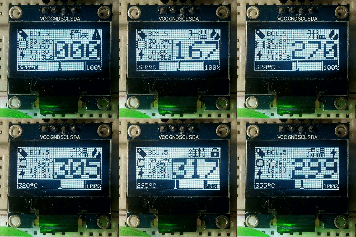
  • 在OLED上实现信息显示
  • Information display on OLED
  • 支持无源蜂鸣器
  • Buzzer
  • 允许设置不同烙铁头的温度校准值
  • Calibrating and managing different soldering tips
  • 设置被保存在EEPROM,掉电不丢失
  • Storing user settings into the EEPROM
  • 允许热插拔烙铁头,并弹出烙铁头配置选择菜单
  • Tip change detection
  • Support for N-Channel and P-Channel MOSFETs

=========UI upgraded version =========

  • 芯片过热以及低电压报警
  • Chip overheating and low voltage alarm
  • 更好的实时温度条以及实时功率条
  • Better real-time temperature bar and real-time power bar
  • 拥有过渡动画
  • Have transition animation
  • 内置屏幕保护程序
  • Built in screen saver
  • 屏幕翻转设置
  • Screen flip settings
  • 内置英文、中文语言包
  • Built in English and Chinese language pack
  • 开机密码设置
  • System Password
  • 允许设置旋钮方向
  • Knob direction setting menu
  • 内嵌看门狗,宕机自动重启
  • Watchdog timer automatic reset the MCU

V1.8t7 New features:

  • EEPROM可用性检查机制

  • EEPROM availability check

  • 允许保存最大30个烙铁头的配置

  • Tip change detection30 preservable soldering tip configurations

  • 9段温度曲线拟合

  • 9 segments of temperature curve fitting

Links:

2. Versions, Upgrades and Notes

Soldering Station v2.0:

IMG_20190731_190146_x.jpg IMG_20190731_182904_x.jpg

Soldering Station v2.5:

IMG_20200621_132138_x2.jpg IMG_20200621_121350_x.jpg

Soldering Station v2.6:

IMG_20200816_141230_x.jpg IMG_20200816_130923_x.jpg

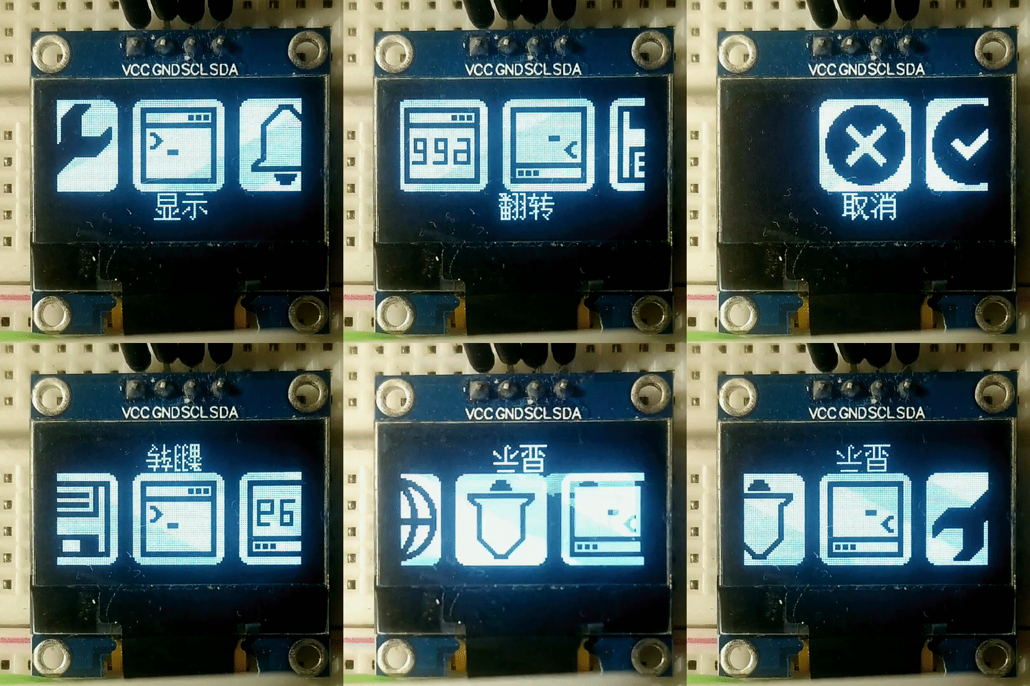
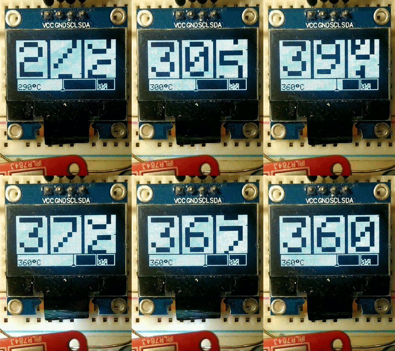
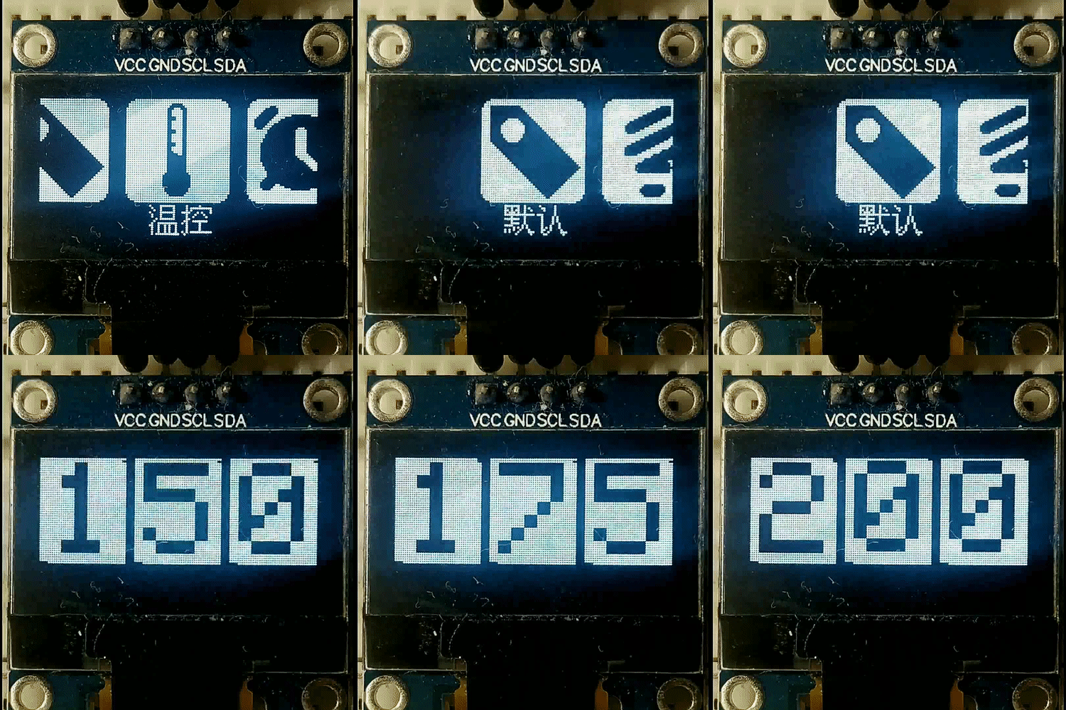
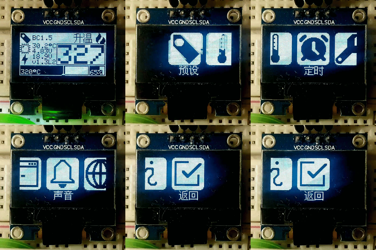
UI-V1.8t6 UI Upgrade by createskyblue & lihaoyun6

Default control interface

EEPROM availability check

Tip menu

9 segments of temperature curve fitting & Soldering tip calibration page

Temperature calibration coefficient

Encoder direction regulation

Video from LHW-createskyblue (UI-v1.6L): https://b23.tv/LiOe54

Notes and Errors

  • In the board version 2.5 the diode D1 may overheat. To be on the safe side, the 18V zener diode D4 should be removed and the soldering station should be operated with a maximum of 20V. Alternatively, the diode D1 can be replaced with an SS54 schottky diode and the BJT Q1 with an FMMT619.

3. Power Supply Specification Requirements

Choose a power supply with an output voltage between 12V and 24V which can provide an output current according to the table below. The power supply must be well stabilized. The current and power is determined by the resistance (R = 8 Ohm) of the heater.

Voltage (U) Current (I) = U / R Power (P) = U² / R
12 V 1.50 A 18 W
13 V 1.63 A 21 W
14 V 1.75 A 25 W
15 V 1.88 A 28 W
16 V 2.00 A 32 W
17 V 2.13 A 36 W
18 V 2.25 A 41 W
19 V 2.38 A 45 W
20 V 2.50 A 50 W
21 V 2.63 A 55 W
22 V 2.75 A 61 W
23 V 2.88 A 66 W
24 V 3.00 A 72 W

4. Temperature Measurement and OpAmp Considerations

A thermocouple (temperature sensor) is located in the T12 soldering tip. It creates a very small voltage depending on the temperature difference between the hot end and the cold junction (about 22 microvolts per degree Celsius). To measure this, the heater must be switched off since both share the same connections. The low voltage is amplified by the OpAmp and measured by the ADC of the microcontroller. The LMV358 is a very cheap and versatile OpAmp, but not the ideal choice for this task because it has a fairly high input offset voltage and is quite noisy. Although the SolderingStation also works with this OpAmp thanks to the software's smoothing and calibration algorithms, I highly recommend spending a little more money in a better one. The OPA2330AIDR or OPA2333AIDR for instance have the same pinout and can also be used with this board. They provide significantly more accurate and stable temperature measurements.

SolderingStationV2_LMV358_Noise.png SolderingStationV2_OPA2330_Noise.png SolderingStationV2_LMV358_SettleTime_2.png SolderingStationV2_OPA2330_SettleTime.png

5. Heater High Side Switch with N-Channel MOSFET and Charge Pump

The microcontroller switches the heater on and off via the MOSFET. Since the temperature measurement must be done over the same line and against ground, the MOSFET has to be placed between the supply voltage and the heater (high-side switch). A P-Channel MOSFET is normally used for this configuration. However, N-Channel MOSFETs usually have a lower resistance (RDS (on)), in the case of the IRLR7843 only 3 milliohms. A low resistance means a higher efficiency and a lower heat development of the MOSFET. For an N-channel MOSFET to function as a high-side switch, an additional circuit is required to maintain a positive GATE-TO-SOURCE voltage after the MOSFET is switched on. This is done using a so-called charge pump consisting of a capacitor and a diode. The principle of operation is illustrated in the following graphic by Smallp Tsai:

chargepump.png SolderingStationV2_ChargePump.png

6. Building Instructions

In addition to the components for the PCB you will need the following:

  • 3D-printed case
  • Aviator Plug (4- or 5-pin depending on your iron handle)
  • DC Power Jack (5.5 * 2.1 mm)
  • Rocker Switch (KCD1 15 * 10 mm)
  • Some wires
  • 4 Self-tapping screws (2.3 * 5 mm)

parts.jpg IMG_20200621_130414_x.jpg

Make sure that all parts fit nicely into the case. Solder the wires to the connectors and protect them with heat shrinks. Use thick wires (AWG18) for the power connections. Make all connections according to the schematic down below but keep in mind, that there's no standard pinout. Solder the wires directly to the corresponding pads on the pcb. To make the soldering station ESD-safe, connect the earth (E) terminal of the aviator plug to a female dupont connector and glue it into the corresponding opening on the case. Now you can connect the soldering station via a male dupont connector to an earth terminal. Upload the firmware and screw the pcb on top of the case.

connections.png

The pinout shown works for the Quecoo handles from aliexpress. Different handles may have different pinouts. If you are assembling your handle yourself, follow the scheme shown below. The video by John Glavinos (electronics4all) shows how it's done.

T12_handle.png

7. License

license.png

This work is licensed under Creative Commons Attribution-ShareAlike 3.0 Unported License. (http://creativecommons.org/licenses/by-sa/3.0/)

atmega-soldering-station's People

Contributors

createskyblue avatar muink avatar taaralabs avatar wagiminator avatar

Stargazers

 avatar  avatar  avatar  avatar  avatar  avatar  avatar  avatar  avatar  avatar  avatar  avatar  avatar  avatar  avatar  avatar  avatar  avatar  avatar  avatar  avatar  avatar  avatar  avatar  avatar  avatar  avatar  avatar  avatar  avatar  avatar  avatar  avatar  avatar  avatar  avatar  avatar  avatar  avatar  avatar  avatar  avatar  avatar  avatar  avatar  avatar  avatar  avatar  avatar  avatar  avatar  avatar  avatar  avatar  avatar  avatar  avatar  avatar  avatar  avatar  avatar  avatar  avatar  avatar  avatar  avatar  avatar  avatar  avatar  avatar  avatar  avatar  avatar  avatar  avatar  avatar  avatar  avatar  avatar  avatar  avatar  avatar  avatar  avatar  avatar  avatar  avatar  avatar  avatar  avatar  avatar  avatar  avatar  avatar  avatar  avatar  avatar  avatar  avatar  avatar

Watchers

 avatar  avatar  avatar  avatar  avatar  avatar  avatar  avatar  avatar  avatar  avatar  avatar  avatar  avatar  avatar  avatar  avatar  avatar  avatar  avatar  avatar  avatar  avatar  avatar  avatar  avatar  avatar  avatar  avatar  avatar  avatar  avatar  avatar  avatar  avatar  avatar  avatar  avatar  avatar  avatar  avatar  avatar  avatar  avatar  avatar  avatar  avatar  avatar  avatar

atmega-soldering-station's Issues

JBC c210 handle

is it possible to use a jbc c210 handle and tip, from what i have seen the jbc only has 3 wires.

Lgt8f328p

Cat you make program to Lgt8f328p (Arduino nano chenese clone on green board)?LGT8.jpeg

T12 Thermocouple uV per degree Celsius question

Hello,
In the readme, it said the delta is roughly 40 uV per degree Celsius
but that is no match to the default calibration temp in firmware.
Please help to correct me If my calculation is wrong.

  1. Vcc = 5V
  2. the gain of opamp is set to 201 (1 + 200K/1K)
  3. default calibration:
    • 200/216 -> (200 * 5 * 1000000) / (1024 * 201 * 216) = 22.49
    • 280/308 -> (280 * 5 * 1000000) / (1024 * 201 * 308) = 22.08
    • 360/390 -> (360 * 5 * 1000000) / (1024 * 201 * 390) = 22.42

so the actual delta should be ~22

Is there any calculation error above?
Please help me to understand the logic.
Thanks !!

No "issue" only a feedback...

A wonderful circuit that is still very relevant... I modified the circuit for a different type of display and it works just great.

However, I changed two things:

I think the thermocouple amplifier is suboptimally designed. In my opinion, the 1uF capacitor at P+ is rather unnecessary and ensures that the entire board "chirps" with the PCM frequency. The filter effect with an 8 ohm heating element is marginal. I also think the 2n2 capacitor is placed suboptimally. Its effect is many times higher when used in parallel with R8 200K and significantly increases stability.

Since the 490 Hz PCM frequency "annoys" me because of the noise, I changed the frequency via

TCCR1B = TCCR1B & B11111000 | B00000100; // for PWM frequency of 122.55 Hz

which just minimizes the "noise nuisance" and has no impact on the function.

A simple single OP LMV321RILT is used as the OP and it really works without any problems.

I think the removal of the switching power supply with the replacement 78M05 a pity... At least with my display/processor, almost 2 watts are "wasted", which increases the temperature significantly. Since I wired the whole thing as a prototype on a stripboard, I installed the 7805, but later connected a typical China stepdown module to reduce the 24 V to 8 V. Since the converter clocks at 1 MHz, this has no measurable impact on the stability of the thermocouple amplifier.

But this is just a suggestion for own experiments/changes...


But also a question on this occasion:

Why is the thermocouple amplified 200 times and the ADC operated at 5 volts. Wouldn't the internal reference of 1.1 volts and significantly lower gain make more sense?

Grounding problem and 12V power supply compatibility

Many DIY T12 Soldering Stations Use Switch Mode Power Supply.
When use an ungrounded SMPS, Y Capacitor can conduct a 50 / 60 Hz AC to metal surface, usually the half of 220 V/ 110 V voltage. Grounding is a easy and effective way to avoid leakage current and circuit damage ( rarely occurs ), but in some cases grounding may not be feasible. ( e.g. buildings lack of PE line rarely )

I have heard many solutions such as:

  • Grounding to metal water pipe
  • Use a battery power supply hardware version
  • Use linear power supply
  • Use antistatic plastic floor
  • Use Isolation transformer

*some of them may not safe and useless

After considering safety and price, I decided to try another way. Use a power bank provide the power to T12 soldering. When using specific cable accessories, QC protocol supported power bank can easily provided 12V voltage, when use a PD protocol supported power bank, it can be higher ( In fact, some hardware versions even use a MacBook power adaptor as power supply and casing of T12 soldering station ). especially the former is much cheaper than series battery packs, and more portable and removable. Connect with a power bank, T12 can be used as a portable soldering station.
I found that some people have tested it on some commercial versions of the DIY T12 soldering station, and it works well except for a slightly longer heating time, even for some of the DC socket versions marked with 16-24 volts.

What about this soldering station?

The document requests power voltage 16V - 24V. Will it works properly at 12V?
If it can work, could you please add 12V power supply specification to the document?

thanks.

Thread size

Hi!What are the parameters of the thread in the 3d model?thank you so much!

charge pump question

Hello,

I am studying your "charge pump" design, please correct me if my understandings are wrong.
Thanks a lot!

(based on board version v2.7)
image

Left:
D9 on -> Q1 on, current go through Q1, so Q2 Vgs is 0, Q2 off.
C7 is charged to full (~24v if ignore D1 voltage drop)

Right:
D9 off -> Q1 off, C7 start to discharge, Q2 Vgs become 24V, Q2 on.
(Vsource = ~23v, Vgate = ~47v)

part requirement:
Q1: Vce need to handle > 47v, therefore choose FMMT619
C7: require > 24V voltage
D1: require > 24V reverse voltage (in discharge scenario)
D4: 18V zener is to protect Q2 gate, IRLR7843 max Vgs = 20V

Thanks.

5V Voltage regulator

Can i use a buck converter (step down) instead of 78m05 for better efficiency and less heat ? thanks

Soldering_Station v2.7 flashed BUT no Output on Display

Dear @wagiminator ,

thanks for the great project.
I managed to build the PCB and solder all components. Flashing process via an Arduino UNO seems successful, but the (new) display stays dark.

avrdude: verifying ...
avrdude: 24006 bytes of flash verified

avrdude: safemode: Fuses OK (E:00, H:00, L:00)

avrdude done. Thank you.

I haven't connected any wires to V,P,E and SW yet, but the display should show something when the board is powered via ICSP right?
Can I test the display in any way?

PID buzzing noises.

I have a strange buzzing noises (not from the buzzer) when using PID controlling, but everything works like a charm.
I cannot find the responsible component. Any help will be appreciated. Thanks

some questions about operate amplifier!!!

first, thank you very much for the answer about last question, i am really a freashman about this field but eager to revive your project, and the procceeding is going to 50%
4AE727C044E1B265C51F398A36A548F7
1D796F8BDC056EE983D3467754629805
5F5803702DF6173CA944CB61677F7360
and now i have some theoretic question about the amplifier, why do you choose such value of risitors and capacitors to amplifing the thermometer value, (if it is possible, may you give a mathematical deduction?) and why does the diode directly connect to the GND? what do you think of the digtal GND and analog GND, why do not you use them to make a segragation so that to supress noise?
image

thanks again!

Compiling upgraded UI

No issues with original code but when compiling the new UI version, I get errors relating to Arduboy2 (6.0.0)...
Just to check, it will compile in Arduino IDE? (1.8.15)...

Errors relate to: TXLED0, TXLED1 not being defined...
Any help appreciated... Mike

Lm358

Can i use Lm358 instead of LMV358 or OPA2333AIDR until i find the parts.
Because it's hard to find them where i live.Thanks

Some questions about P+

image
the P+ net actually directly connects with GND, is that correct? hope to get a reasonable answer, thanks

chinese clone handle compatibility

Hi,

is your aviator plug wiring compatible with the chinese handle?
It's a bit confusing.
for example + is pin 2 and - pin 5 & 4.
on the ksger clone & other i see + is pin 5 & ground pin 4.
as you can see here ksger

Recommend Projects

  • React photo React

    A declarative, efficient, and flexible JavaScript library for building user interfaces.

  • Vue.js photo Vue.js

    🖖 Vue.js is a progressive, incrementally-adoptable JavaScript framework for building UI on the web.

  • Typescript photo Typescript

    TypeScript is a superset of JavaScript that compiles to clean JavaScript output.

  • TensorFlow photo TensorFlow

    An Open Source Machine Learning Framework for Everyone

  • Django photo Django

    The Web framework for perfectionists with deadlines.

  • D3 photo D3

    Bring data to life with SVG, Canvas and HTML. 📊📈🎉

Recommend Topics

  • javascript

    JavaScript (JS) is a lightweight interpreted programming language with first-class functions.

  • web

    Some thing interesting about web. New door for the world.

  • server

    A server is a program made to process requests and deliver data to clients.

  • Machine learning

    Machine learning is a way of modeling and interpreting data that allows a piece of software to respond intelligently.

  • Game

    Some thing interesting about game, make everyone happy.

Recommend Org

  • Facebook photo Facebook

    We are working to build community through open source technology. NB: members must have two-factor auth.

  • Microsoft photo Microsoft

    Open source projects and samples from Microsoft.

  • Google photo Google

    Google ❤️ Open Source for everyone.

  • D3 photo D3

    Data-Driven Documents codes.