pgf-tikz / pgf Goto Github PK
View Code? Open in Web Editor NEWA Portable Graphic Format for TeX
Home Page: https://pgf-tikz.github.io/
A Portable Graphic Format for TeX
Home Page: https://pgf-tikz.github.io/


![dependabot[bot] avatar](https://avatars.githubusercontent.com/in/29110?v=4 "dependabot[bot]")


Migrated from SourceForge
Author: *anonymous
Timestamp: 2005-09-29 14:07:09
In the line starting with "dvips" the first variable is
:
dvips -o
Migrated from SourceForge
Author: lakedaemon
Timestamp: 2007-05-03 20:49:52
As says this document
http://www.w3.org/TR/XHTMLplusMathMLplusSVG/
it is possible to mix xhtml, mathml and svg.
What is even more interesting is the possibility to use the foreignobject element to embbed Xhtml code and mathml code in a svg picture :
This resolves the limited support for text in nodes for the pgfsys-tex4ht driver and brings power to the masses (^_^) :
this brings the web to the era of scalable graph with technical annotations or to text that his formated inside artistically designed svg boxes.
Well, Firefox 1.5+ supports SVG and mathml
and Firefox 3 which should be released in just a few months should support this "foreignobject" element that makes this possible
(actually, the nightly builds of firefox already support it, I tested it and it looked really fine (and easy to use)
(let's hope that opera, internet explorer, safari and others will support it soon too...)
Now, the feature that I would like pgf to have (if it hasn't already have it) is the ability to specify the svg namespace in the file.svg that it exports.
say the ability to write
<svg:svg>
<svg:g>
..
..
</svg:g>
instead of
<svg>
<g>
..
..
</g>
It would be nice to have (in pgfsys-tex4ht.def ?) either an option xhtml for nodes or a special \xhtmlnode command (with sub-options x y width height) that tells it to just
writes
<svg:switch><foreignobject x=".." y=".." width=".." height="..">tex4ht xhtml+mathml code </foreignobject>
</svg:switch>
Migrated from SourceForge
Author: fstengel
Timestamp: 2006-06-12 20:33:56
Idea by cuomo in ``relative polar coordinates''. I paraphrase cumo's
original post
``Would it be possible to specify relative polar coordinates in tikz? By
relative I mean that the specified angle should be relative to the angle
which is created by the two previous points. For example:
\draw (0,0) -- (0,1) -- +(90:1cm);
should give a corner, not a long line.''
I added by proposing a tentative syntax for this :
\draw (0,0) -- (0,1) -- +*(90:1cm);
to replace
\draw (0,0) -- (0,1) -- +(-1,0);
or
\draw (0,0) .. controls +*(10:1cm) and +*(-10:-1cm) .. (2,2);
to replace
\draw (0,0) .. controls +(55:1cm) and +(35:-1cm) .. (2,2);
One would also have a ++*. The * notation could also be used with
standard vectors: +*(1,1) meaning something like +*(45:1.414cm) with
the default unit...
PS would it be possible to attribute this request to cuomo?
Migrated from SourceForge
Author: tiger74_06
Timestamp: 2006-10-22 09:04:46
Hi there, I'd like to know a convenient code in PGF to
create framed environments for remarks, theorems,
definitions,... like the ones given in Beamer using PGF
for a latex file compiled using pdflatex. An example of
what I want is given in chapter 1 of:
https://www.ita.uni-heidelberg.de/internal/c++course/cppscript.pdf
(the author may have probably used context and not
latex, I've tried to contact one of the authors of the
book but no luck so far).
The most important part is to know if it's possible to
make a smart script that allows the frame environment
to be cut when a new page is necessary. Also, it is
possible to add shadows to the frame box as in Beamer?
Please let me know of any ideas to get this done.
Thanks,
Ruben.
Migrated from SourceForge
Author: fstengel
Timestamp: 2006-01-21 18:32:20
First: thanks for pgf...
Could it be possible to consider a function plot a a single path and permit
constructs such as
\draw plot[id=f] function{x**2*sin(x)} node[pos=0.5, above, yshift=3pt]
{$f(x) =x^2\sin(x)$};
This makes labelling of plots a bit easier...
I do understand that the placement would be rather rough: one can only
interpolate the actual position...
Migrated from SourceForge
Author: *anonymous
Timestamp: 2007-05-12 20:16:45
It would be great to have a better layout algorithm for trees.
Pstricks computes a left and right profile for each subtree,
and fits them as close together as possible without overlapping.
thanks!
Migrated from SourceForge
Author: *anonymous
Timestamp: 2007-05-02 10:23:07
If you want to implement xyz coordinates that are not the usual ones, like for example having the x, y and z axes at equal angles, it is tricky to put together. If you say
\begin{tikzpicture}[x={(-.866,-.5)},y={(.866,-.5)},z={(0,1)}]
this should do the trick. But it doesn't work, because the system first changes the x axis to point in the indicated direction, and then changes the y axis in terms of the new x axis. What I would like is that the coordinates appearing in x={...} are set against some background (X,Y) coordinate system, which remains fixed, so that x={..} commutes with y={..}. In other words, so that x={(3,2)} sets x axis to (3,2) in the (X,Y) system. Then following with y={(1,2)} would set y to (1,2) in the (X,Y) system. This makes it much easier to work with xyz coordinates for 3 dimensional pictures.
Migrated from SourceForge
Author: lakedaemon
Timestamp: 2007-05-03 10:34:45
bug and workaround for cvs version of tikz with !TeX and tex4ht
tex4ht defines everypar={\Htmlpar}
so that it inserts \Hcode{</p><p>} at every paragraph in vboxes...
now, nodes with text work fine in tikz+TeX+tex4ht as long as you don't specify a "text width" option...
in which case it uses an minipage emulation for TeX and puts the text inside a vbox and that produces invalid svg code as the vbox starts with a paragraph and so tex4ht puts </p><p> in the svg code...
A workaround for that would be to code it like
{\everypar={}%
\tikzpicture
picture with nodes with minipage emulation in TeX
\endtikzpicture
}%
or like
{
\catcode`:=11
:nopartrue% this is a switch to prevent
%tex4ht inserting </p><p> code at every paragraph
\catcode`:=12
\tikzpicture
picture with nodes with minipage emulation in TeX
\endtikzpicture
}%
both these solutions work in XeTeX and should work with TeX too.
Migrated from SourceForge
Author: *anonymous
Timestamp: 2007-04-13 13:17:10
Hello,
For mathematical pictures one often indicates points with a labeled dot. For example:
\tikz \draw[fill=black]
(1,0) circle (2pt) node[above right] {$A$}
(2,1) circle (2pt) node[above right] {$B$}
(3,-1) circle (2pt) node[above right] {$C$};
But this approach has the following drawbacks:
* If a picture is scaled, the points get scaled
as well.
* Its hard to replace the dots later by an other
symbol, like a square.
The dots are more like marks or arrow tips and should have a consistent look over all pictures of a document. Therefore these dots should not scale with the picture. And it should be possible to change the appearance of these dots using styles.
The following code can be used to solve this problem:
\tikzstyle{point}=
[mark=*,mark options={shift only},only marks]
\tikz \draw plot[point]
coordinates{(1,0) (2,1) (3,-1)};
But this approach is quite awkward and its tedious to label the dots.
I propose a shape called 'dot' or similar to draw labeled points. The shape of a dot can be specified by 'plot marks' and their associated options. For example:
\tikzstyle{point}=
[shape=dot,mark=*,mark options={shift only}]
\tikz \path
(1,0) node[point,label=above right:$A$] {}
(2,1) node[point,label=above right:$B$] {};
What do you think of this idea? Or maybe even the coordinate shape could be used for this purpose?
best regards,
Björn
Migrated from SourceForge
Author: gvdgdo
Timestamp: 2005-09-29 23:05:09
edges in trees are decorated with arrows in what it
seems to me to be the wrong direction (and position)
when trees grow up, and the direction of the arrow is
from child to parent.
The problem seems to be that
\tikzstyle{edge from parent}{draw.<-}
is not recursive
In addition the tree algorithm does not use the right
spaces for leaves of tree og height greater than 2.
here is the code
\begin{tikzpicture}
\tikzstyle{edge from parent}=[draw,<-]
\node {A}
child { node {B}
child { node {C}}
child { node {D}}
}
child { node {E}
child { node {F}}
child { node {G}}
};
\end{tikzpicture}
Package: pgfrcs 2005/09/08 v0.97 (rcs-revision 1.4)
Package: pgf 2005/09/05 v0.97 (rcs-revision 1.4)
pgfcorearrows.code.tex 2005/07/10 (rcs-revision 1.2)
Package: tikz 2005/09/07 v0.97 (rcs-revision 1.24)
Migrated from SourceForge
Author: *anonymous
Timestamp: 2007-05-16 17:38:58
Allow the draft option to be used with the tikz package, to be passed on to pgf.
Migrated from SourceForge
Author: sauert
Timestamp: 2006-07-20 22:20:24
First of all, let me thank you for writing pgf and
tikz and sharing it. They are wonderful to produce
high quality pictures in scientific publications.
During my experiments I found a behaviour with I
think is a bug. Let my give you a minimum example:
\documentclass{article}
\usepackage{tikz}
\begin{document}
\begin{tikzpicture}[x=0.1cm,y=6cm]
\newlength{\xunit}\pgfextractx{\xunit}
{\pgfpointxy{1}{0}}
\newlength{\yunit}\pgfextracty{\yunit}
{\pgfpointxy{0}{1}}
\draw[black] (0,0) rectangle (100,3);
\draw[red,dashed] (0\xunit,0\yunit) rectangle
(100\xunit,3\yunit);
\end{tikzpicture}
\end{document}
From my understanding of the manual both rectangles
should be plotted on top of each other. However, they
don't.
I think this is related to the factor 1.00374 inside
\pgfextract*. Unfortunately, I was not able to figure
out, what this multiplication is good for.
Yours Bastian
Migrated from SourceForge
Author: *anonymous
Timestamp: 2005-07-21 05:27:00
[v0.96]
I tried to compile the first example on page 105 of the
manual. But I get the following error message when
compiling using pdflatex:
!Undefined control sequence.
<recently read> \pgfpagelayout
l.3 \pgfpagelayout{2 on 1}[a4paper,landscape,border
shrink=5mm]
Other beamer examples that made use of pgf compiles
without error.
Edmund Lai
Email: [email protected]
Migrated from SourceForge
Author: *anonymous
Timestamp: 2007-05-16 09:21:34
Hello.
Up to our understanding, the three lines in the example given below should all be the same (at least the green and the yellow one).
In fact, neither two of them are.
Greetings from Berlin
\begin{figure}[htpb]
\centering
\begin{tikzpicture}
\draw (0,2) node [draw,rectangle, minimum width=5cm] (n1) {n1};
\draw (0,0) node [draw,rectangle, minimum width=5cm] (n2) {n2};
\path[draw=green] (n2.north) + (1,0) -- ([shift={(1,0)}]n1.south);
\path[draw=yellow, shift={(1,0)}] (n2.north) -- (n1.south);
\path[draw=red] (n2.north) + (1,0) -- (n1.south) + (1,0);
\end{tikzpicture}
\end{figure}
Migrated from SourceForge
Author: *anonymous
Timestamp: 2007-02-23 18:28:43
The minimal example below (using v1.10 of the pgf package) works fine for pdflatex, but latex+dvips cause a ghostscript error. The problem only seems to occur when using both \pgfsetfillopacity and \pgfseteorule. The resulting postscript contains the command "eofill1" whereas I think it should be "eofill 1", which I think is causing the problem.
\documentclass{article}
\usepackage{pgf}
\begin{document}
\begin{pgfpicture}
\pgfsetfillcolor{blue}
\pgfsetfillopacity{1.0}
\pgfseteorule
\pgfpathrectangle{\pgforigin}{\pgfpoint{1in}{1in}}
\pgfusepath{fill}
\end{pgfpicture}
\end{document}
Regards
Nicola Talbot
[email protected]
Migrated from SourceForge
Author: homberghp
Timestamp: 2005-12-11 15:58:43
usepackage{tikz}
causes the following failure
! Undefined control sequence.
l.658 \pgfsetsnakesegmenttransformation
{\pgf@snake@mirror\pgf@snake@raise}
?
during a latex run.
Installation suse Linux 10. Verified on suse9.3 too)
Current hack (which works for me this far)
comment out the offending line in
generic/pgf-1.01/generic/pgf/frontendlayer/tikz.code.tex
Kind regards, I am impressed with the package and even
more so with the documentation in the manual. Greetings
to Karl and Gerda
Migrated from SourceForge
Author: vilarneto
Timestamp: 2007-01-30 16:04:47
Hello,
Recently I've noticed a strange interaction between scopes and snakes. It appears that the lower-left corner of a rectangle with snaked borders doesn't obey scoped translations. A minimum example file follows:
----------
\documentclass[a4paper,11pt]{article}
\usepackage{tikz}
\usetikzlibrary{snakes}
\begin{document}
\begin{tikzpicture}
\begin{scope}[yshift=1cm]
\draw [snake=zigzag] (2,2) rectangle (4,4);
\end{scope}
\end{tikzpicture}
\end{document}
----------
I'm also sending the resulting PDF file. It appears that only that corner ignores the yshift configuration.
I'm using PGF and TikZ v1.10 under Windows MiKTeX, latest version. The problem is the same no matter if compiled with pdflatex or through latex+dvips.
Migrated from SourceForge
Author: *anonymous
Timestamp: 2006-01-04 14:00:54
It appears that in Tikz1.01 decimal angles are not
allowed. Minimal example:
******************************************
\documentclass{article}
\usepackage{tikz}
\begin{document}
\begin{tikzpicture}
\draw (157.5:0.8cm) node {The problem};
\end{tikzpicture}
\end{document}
****************************************
Compiled with pdflatex or latex this gives an error
within the 'calc' package. When the angle is an
integer everything is ok.
A. van der Lee ([email protected])
Migrated from SourceForge
Author: rolfn
Timestamp: 2006-09-07 12:40:05
It would be nice to have an environment similar to
pstricks' "psmatrix": nodes in a array without any
coordinates. The placing should be done by the
environment in the same way like "array". The node
names should be automatically generated: "<row><col>"
(maybe with a prefix).
...Rolf
Migrated from SourceForge
Author: *anonymous
Timestamp: 2006-08-02 12:49:17
Thanks for writing TikZ,
I have just discovered it and I really like it.
However, I found one problem. When I nest a tikz-
picture inside another, the scale-settings are
ignored. Further, I cannot set scales for the nested
tikz environment.
Below is an example to demonstrate it:
\begin{tikzpicture}[scale=5]
\draw [->] (0,0) -- node[midway, above=2mm] {This
arrow has length 1 on scale 5} (1,0);
\draw (0,-.5) node[draw] {
This node has tikx-picture inside its text
\begin{tikzpicture}[scale=10] %scale is
ignored for tikz inside tikz
\draw [->] (0,0) -- node[midway, above=2mm]
{This arrow has length 1 on scale 1??} (1,0);
\end{tikzpicture}
};
\end{tikzpicture}
Another remark: for plotting graphs, it would be
useful if the markers would not scale. Currently,
scaling x and y differently results in asymetrically
drawn markers.
Kind regards,
Bas Verheijen
Migrated from SourceForge
Author: *anonymous
Timestamp: 2006-02-27 19:12:39
I was looking into the code and found what I guess is a
typo: it says "\coordiante" instead of "\coordinate". I
don't know what effect this could have
tikz.code.tex, v1.35, line 963:
\let\tikz@orignode=\coordiante%
there are also two instances of "coordiante" in the
comments of pgfsys.code.tex and systemlayer/pgfsys-
textures.def
Migrated from SourceForge
Author: mvdongen
Timestamp: 2007-05-14 14:29:38
Dear maintainers,
I'd like to make a request for a \node<at> .... option, which is currently not available in pgf (1.10).
Thanks in advance for your efforts.
Regards,
Marc van Dongen
Migrated from SourceForge
Author: *anonymous
Timestamp: 2006-07-20 23:01:29
In some plots I draw with tikz I have so many points
placed tightly next to each other that the plot
becomes complex if plot marks are placed for each
point. In this cases it would be great if it would
be possible to place marks of every other point (or
even less frequent). On the other hand I would like
to avoid to create the plot files and the \plot
commands twice, one for the line with every point and
one for the marks with fewer points.
I created the attached patch/work around, with does
the trick for me for now. It allows the user to
choose to plot only every second mark (starting with
a shown or with a hidden mark).
The patch, however, is probably not the smartest way
and for sure not the most general way to accomplish
this.
Here is a example of what can be done with the patch:
\documentclass{article}
\usepackage{tikz}
\begin{document}
\begin{tikzpicture}[mark=x]
\draw plot coordinates {(0,0) (1,0) (2,0)};
\pgfsetshowfirstplotmark
\draw plot coordinates {(0,1) (1,1) (2,1)};
\pgfsethidefirstplotmark
\draw plot coordinates {(0,2) (1,2) (2,2)};
\pgfsetshowallplotmarks
\draw plot coordinates {(0,3) (1,3) (2,3)};
\end{tikzpicture}
\end{document}
Yours Bastian
Migrated from SourceForge
Author: f_wenzel
Timestamp: 2006-08-18 09:46:49
Hi, Till!
Today, I spotted a bug in pgf which I hope is easy to
fix: If I use pgf along with htlatex and hyperref as
well, "htlatex test.tex" (see sample below) stops with
an error message:
! Package xkeyval Error: `tikz' undefined in families `*'.
This problem only occurs with htlatex, it does not
occur with pdflatex or "plain" latex. I am using the
newest MiKTex distribution 2.5.
If I remove hyperref from my document, all compiles
well, but then (of course) I cannot use statements like
href or url which I have in my documents.
Do you know a solution?
Thanks and greetings from Hamburg,
Fabian
Migrated from SourceForge
Author: *anonymous
Timestamp: 2005-12-02 19:23:38
First, thanks a lot for the great package pgf/tikz!
It would be nice, if there were some command like the
MetaPost angle operator, and some routines for drawing
a path
(I am geometry teacher). The user's manual for MetaPost
(page 47) may give some further ideas.
Thanks in advance,
Cristian
Migrated from SourceForge
Author: kovidgoyal
Timestamp: 2006-04-18 23:56:24
Hi,
When trying to use tikz (current CVS) inside a cases
environment, the document fails to compile (pdflatex
3.141592-1.30.5-2.2 (Web2C 7.5.5)). Test case:
\documentclass{article}
\usepackage{tikz,amsmath}
\begin{document}
\begin{equation}
\tikz{\fill[ball color=green] (0,0) circle (0.1cm);}%
\begin{cases}
\tikz{\fill[ball color=green] (0,0) circle (0.1cm);}
\end{cases}
\end{equation}
\end{document}
Error message:
! Package tikz Error: Cannot parse this radius.
See the tikz package documentation for explanation.
Type H <return> for immediate help.
...
l.7 ...ll[ball color=green] (0,0) circle (0.1cm);}
Thanks,
Kovid.
Migrated from SourceForge
Author: *anonymous
Timestamp: 2005-09-29 14:17:43
https://sourceforge.net/p/pgf/bugs/_discuss/thread/4f3b9236/5bd1/attachment/mwe6.tex
When building the manual with
the resulting PDF is broken.
When turning to page 84 with acrobat 7 the
following wrror message is shown: "Could not find
the Extended Graphics State named 'pgf@ca05'"
This might be caused by the fact that dvipdfm
produces a PDF of version 1.2 which doesn't
support transparency at all.
Migrated from SourceForge
Author: *anonymous
Timestamp: 2007-03-05 18:15:00
I like to use, whenever possible, the route latex + dvipdfmx. In order for this to work with tikz, I have to explicitly add "\def\pgfsysdriver{pgfsys-dvipdfm.def}", but otherwise everything seems to be fine, except for one little quirk. When I do this, the pdftitle/pdfauthor/pdfsubject information that I set with hyperref is not transferred to the pdf file.
By the way, I do not know whether it is just an alias, but now the "dvipdfmx" (as opposed to "dvipdfm") option is recognized by both hyperref and graphicx. If it is not a mere alias, ie there is some nontrivial extension, maybe it might also be incorporated to pgf.
Thanks very much for such a great program!
Migrated from SourceForge
Author: torquilmacd
Timestamp: 2007-03-16 00:32:55
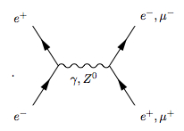
Hello,
In physics, Feynman diagrams are often used, which need "arrowheads" halfway along the lines/curves, as in this example:
http://osksn2.hep.sci.osaka-u.ac.jp/~taku/osx/img/tree.jpeg
It would be useful to be able to do this with PGF/TikZ, for all the different line types in pgflibrarysnakes. One could then use PGF/TikZ to make Feynman diagrams. Right now everyone uses the feynmf/feynmp packages, but these don't work with pdflatex.
Best regards,
Torquil M. Sørensen
Migrated from SourceForge
Author: piefel
Timestamp: 2006-12-08 11:04:03
The pgfpages packages contains the very nice option to print 8 on 1 etc. However, the pages are evenly distributed on the paper and too close. Using border shrink=5mm shrinks the slides, but not in a very useful way: There is a lot of space between the slides (particularly in the vertical middle) but little on the page borders.
I use the following code:
\pgfpagesdeclarelayout{8 on 1 (border)}
{
\edef\pgfpageoptionheight{\the\paperwidth} % landscaped by default
\edef\pgfpageoptionwidth{\the\paperheight}
\def\pgfpageoptionborder{0pt}
}
{
\pgfpagesphysicalpageoptions
{%
logical pages=8,%
physical height=\pgfpageoptionheight,%
physical width=\pgfpageoptionwidth%
}
\ifdim\paperheight>\paperwidth\relax
% put side-by-side
\pgfpageslogicalpageoptions{1}
{%
border shrink=\pgfpageoptionborder,%
resized width=.25\pgfphysicalwidth,%
resized height=.5\pgfphysicalheight,%
center=\pgfpoint{.1625\pgfphysicalwidth}{.725\pgfphysicalheight}%
}%
\pgfpageslogicalpageoptions{2}
{%
border shrink=\pgfpageoptionborder,%
resized width=.25\pgfphysicalwidth,%
resized height=.5\pgfphysicalheight,%
center=\pgfpoint{.3875\pgfphysicalwidth}{.725\pgfphysicalheight}%
}%
\pgfpageslogicalpageoptions{3}
{%
border shrink=\pgfpageoptionborder,%
resized width=.25\pgfphysicalwidth,%
resized height=.5\pgfphysicalheight,%
center=\pgfpoint{.6125\pgfphysicalwidth}{.725\pgfphysicalheight}%
}%
\pgfpageslogicalpageoptions{4}
{%
border shrink=\pgfpageoptionborder,%
resized width=.25\pgfphysicalwidth,%
resized height=.5\pgfphysicalheight,%
center=\pgfpoint{.8375\pgfphysicalwidth}{.725\pgfphysicalheight}%
}%
\pgfpageslogicalpageoptions{5}
{%
border shrink=\pgfpageoptionborder,%
resized width=.25\pgfphysicalwidth,%
resized height=.5\pgfphysicalheight,%
center=\pgfpoint{.1625\pgfphysicalwidth}{.275\pgfphysicalheight}%
}%
\pgfpageslogicalpageoptions{6}
{%
border shrink=\pgfpageoptionborder,%
resized width=.25\pgfphysicalwidth,%
resized height=.5\pgfphysicalheight,%
center=\pgfpoint{.3875\pgfphysicalwidth}{.275\pgfphysicalheight}%
}%
\pgfpageslogicalpageoptions{7}
{%
border shrink=\pgfpageoptionborder,%
resized width=.25\pgfphysicalwidth,%
resized height=.5\pgfphysicalheight,%
center=\pgfpoint{.6125\pgfphysicalwidth}{.275\pgfphysicalheight}%
}%
\pgfpageslogicalpageoptions{8}
{%
border shrink=\pgfpageoptionborder,%
resized width=.25\pgfphysicalwidth,%
resized height=.5\pgfphysicalheight,%
center=\pgfpoint{.8375\pgfphysicalwidth}{.275\pgfphysicalheight}%
}%
\else
% stack on top of one another
\pgfpageslogicalpageoptions{1}
{%
border shrink=\pgfpageoptionborder,%
resized width=.5\pgfphysicalwidth,%
resized height=.25\pgfphysicalheight,%
center=\pgfpoint{.275\pgfphysicalwidth}{.8375\pgfphysicalheight}%
}%
\pgfpageslogicalpageoptions{2}
{%
border shrink=\pgfpageoptionborder,%
resized width=.5\pgfphysicalwidth,%
resized height=.25\pgfphysicalheight,%
center=\pgfpoint{.725\pgfphysicalwidth}{.8375\pgfphysicalheight}%
}%
\pgfpageslogicalpageoptions{3}
{%
border shrink=\pgfpageoptionborder,%
resized width=.5\pgfphysicalwidth,%
resized height=.25\pgfphysicalheight,%
center=\pgfpoint{.275\pgfphysicalwidth}{.6125\pgfphysicalheight}%
}%
\pgfpageslogicalpageoptions{4}
{%
border shrink=\pgfpageoptionborder,%
resized width=.5\pgfphysicalwidth,%
resized height=.25\pgfphysicalheight,%
center=\pgfpoint{.725\pgfphysicalwidth}{.6125\pgfphysicalheight}%
}%
\pgfpageslogicalpageoptions{5}
{%
border shrink=\pgfpageoptionborder,%
resized width=.5\pgfphysicalwidth,%
resized height=.25\pgfphysicalheight,%
center=\pgfpoint{.275\pgfphysicalwidth}{.3875\pgfphysicalheight}%
}%
\pgfpageslogicalpageoptions{6}
{%
border shrink=\pgfpageoptionborder,%
resized width=.5\pgfphysicalwidth,%
resized height=.25\pgfphysicalheight,%
center=\pgfpoint{.725\pgfphysicalwidth}{.3875\pgfphysicalheight}%
}%
\pgfpageslogicalpageoptions{7}
{%
border shrink=\pgfpageoptionborder,%
resized width=.5\pgfphysicalwidth,%
resized height=.25\pgfphysicalheight,%
center=\pgfpoint{.275\pgfphysicalwidth}{.1625\pgfphysicalheight}%
}%
\pgfpageslogicalpageoptions{8}
{%
border shrink=\pgfpageoptionborder,%
resized width=.5\pgfphysicalwidth,%
resized height=.25\pgfphysicalheight,%
center=\pgfpoint{.725\pgfphysicalwidth}{.1625\pgfphysicalheight}%
}%
\fi
}
It differs from the original only in the center lines and is usable only with a skrunk border; IOW it is a hack. It would be much better to have some kind of option for this built-in into PGF.
Migrated from SourceForge
Author: *anonymous
Timestamp: 2005-10-27 17:28:34
The file pgfsys-vtex.def is missing in the pgf-1.00
distribution.
Migrated from SourceForge
Author: eric_detrez
Timestamp: 2007-04-20 17:25:37
When I use plain Tex and try to plot a function with the help of Gnuplot I got an error in the process. In fact if I hit the enter key a dozen times to overpass the error messages I eventualy got the right result.
Here is a tex file that gives the problem
*******************
\input tikz.tex
\tikzpicture[domain=0:7]
\draw plot[id=fonc] function{x} node[right] {$y=f(x)$};
\endtikzpicture
\end
*******************
This doesn't occur when I use LaTeX ;
*******************
\documentclass{article}
\usepackage{tikz}
\begin{document}
\begin{tikzpicture}[domain=0:7]
\draw plot[id=fonc] function{x} node[right] {$y=f(x)$};
\end{tikzpicture}
\end{document}
*******************
The log file is attached.
Migrated from SourceForge
Author: *anonymous
Timestamp: 2006-12-21 15:21:39
Trying out TikZ's "mindmap" library, I figured that it requires the "trees" library to be loaded as well. This is not documented.
Reason is that the default style applies settings to "sibling angle" which is declared in "trees".
Regards,
-- Marcus <[email protected]>
Migrated from SourceForge
Author: *anonymous
Timestamp: 2005-11-23 19:10:45
First of all,thanks for the great job you're doing with
pgf/tikz!
It would be nice, if there were some standard routines
to draw different kinds of coordinate axes (e.g. Maples
boxed, frame, normal) including ticmarks and labels.
pst-plot has at least some support for it and gri may
give some additional ideas.
It don't know if a shape is the right thing to
implement such a functionality in pgf/tikz.
Kind regards,
Markus
Migrated from SourceForge
Author: jlvm
Timestamp: 2006-09-14 18:23:37
Thanks for tikz/pgf. It's great.
I suggest the possibility of use something like
node[below = 3pt, left=-2pt]{...}
As long as I know, it is not possible to make something like
node[below left= number pt]{...}
so it is not possible to make different adjustment for below and left.
It would be very useful for small adjustment of labels in the nodes.
And I suppose that it will be easy to implement.
(Of course, the same can be applied to below and right)
Yours,
Juan Luis Varona
jvarona at dmc point unirioja point es
Migrated from SourceForge
Author: *anonymous
Timestamp: 2006-03-21 18:43:52
I received a message:
!Undefined control sequence.
I.658 \pgfsetsnakesegmenttransformation
{\pgf@snake@mirror\pgf@snake@raise}
After that it is impossible to compile some examples:
\draw[step=.5cm,gray,very thin] (-1.4,-1.4) grid (1.4,1.4);
! Package tikz Error: I do not know what to do with the option ``line
width={0.
2pt}''.
See the tikz package documentation for explanation.
Type H <return> for immediate help.
...
l.19 \draw[step=.5cm,gray,very thin]
(-1.4,-1.4) grid (1.4,1.4);
Migrated from SourceForge
Author: *anonymous
Timestamp: 2005-11-13 02:44:27
I'm using pgf almost daily for its impressive quality.
However, one major disadvantage is that I need to
compile the latex file to know I really drawed in pgf.
I't will be great if there is an easy way to preview
the pgf pictures.
Migrated from SourceForge
Author: lakedaemon
Timestamp: 2007-05-07 17:21:26
would it be possible to have a text along path macro implemented in tikz ?
I don't know if it is possible to easily render such a thing in pdf but the svg specification allows it (with the textpath element) as you can see (with firefox 2) here :
http://www.w3.org/TR/SVG/images/text/toap01.svg
Migrated from SourceForge
Author: *anonymous
Timestamp: 2005-07-22 20:34:01
Hi,
Thee command \pgfplotxyfile does not read numbers like
".692428e-3" correctly
I get the following error:
! Illegal unit of measure (pt inserted).
<to be read again>
e
Thanx, pgf and TikZ are great.
Migrated from SourceForge
Author: lakedaemon
Timestamp: 2007-04-18 12:17:15
Could you please change Tikz so that it provides infix arithmetic for TeX too (no reason why the LaTeX guys should have all the fun) ?
I posted explanations and a port to TeX of the LaTeX package Calc in the help forum.
Migrated from SourceForge
Author: *anonymous
Timestamp: 2007-04-11 09:47:46
Hello,
I think that the current transformation should not be applied to the plot marks of a picture.
Similar to arrow tips, plot marks should not scale when the picture is scaled. This way the plot marks of all pictures of a document are of equal size, like the arrow tips. Thus the pictures of a document look more consistent.
In order to change the size of plot marks, the option 'mark size' can be used. Or one can specify a transformation in the 'mark options' option.
I think this is a reasonable change to pgf, isn't it?
Thanks for creating PGF/TikZ.
Best regards
Björn
Migrated from SourceForge
Author: fstengel
Timestamp: 2006-01-21 18:40:46
In xy there is an interesting option that permits one to design curved
paths that slightly deviate from a straight path. In Tikz, an example could
be
\path[draw, curved left=5pt] (0,0) -- (1,0);
\path[draw, curved right=2mm] (0,0) -- (1,1);
which would be (roughly) equivalent to (I am assuming the unit is 10mm)
\path[draw] (0,0) .. controls (0.5,5pt) .. (1,0);
\path[draw] (0,0) .. controls (6.41mm,3.59mm) .. (1,1);
the argument of curved left/right would denote a deviation of that
distance orthogonally from the mid-moint of the straight line...
All that to simplify the drawing of directed graphs...
Migrated from SourceForge
Author: altermundus
Timestamp: 2006-11-20 18:52:22
\documentclass[]{article}
\usepackage{tikz}
\usepackage[frenchb]{babel}
\begin{document}
\begin{tikzpicture}
\tikzstyle{vertex}=[shape=circle,%
draw=black,%
fill=gray!30,
minimum size =1cm]
\node[vertex,label=above:$a$]
\end{tikzpicture}
\end{document}
vertex,label=above:$a$,\end {tikzpicture}
./try_label.tex:17: Paragraph ended before \tikz@fig@scan@options was complete.
@safe@activestrue is needed
Actual solution : \shorthandoff{:}
Alain Matthes
Migrated from SourceForge
Author: lakedaemon
Timestamp: 2007-05-03 10:02:49
In the cvs version of pgf, in file "pgfmathcalc.code.tex",
at line 59
(in the definition of macro \pgfmathnewcounter),
the control sequence "\newcount" which is declared "outer" by the plain format causes an error at compile time...for TeX and friends.
Now, if you change it to "\innernewcount" (a variant of \newcount that can be used inside macro definitions),
it then works flawlessly...(as tested in XeTeX).
Migrated from SourceForge
Author: *anonymous
Timestamp: 2006-04-19 21:37:37
Hi,
When using
tikz.sty 2005/10/18 v1.00 (rcs-revision 1.32)
pgf.sty 2005/09/05 v1.00 (rcs-revision 1.4)
I get a reversed '-latex' arrow tip, while the '->'
arrow tip is fine:
\documentclass{article}
\usepackage{tikz}
\begin{document}
\begin{tikzpicture}[scale=0.5,very thick,-latex,rotate=90]
\draw (1.5,1.5) parabola bend (0,0) (-1.5,1.5);
\draw (2,0) -- (-2,0);
\end{tikzpicture}
\qquad
\begin{tikzpicture}[scale=0.5,very thick,->,rotate=90]
\draw (1.5,1.5) parabola bend (0,0) (-1.5,1.5);
\draw (2,0) -- (-2,0);
\end{tikzpicture}
\end{document}
cheerio
ralf
[email protected]
Migrated from SourceForge
Author: equaeghe
Timestamp: 2006-02-22 21:53:21
Currently, backgrounds can be added to tikzpictures,
but not to scopes.
To use backgrounds, one just has to additionally use
\usetikzlibrary{backgrounds}
in the preamble.
An example:
\begin{tikzpicture}[framed]
\draw (0,0) -- (1,1);
\end{tikzpicture}
This gives a framed picture.
As a scope can be seen and used as a logical sub-picture, it seems useful to also implement this functionality there, so one could write:
\begin{tikzpicture}
    \draw (0,0) -- (1,1);
    \begin{scope}[framed, xshift=2cm]
        \fill (0,0,1) circle (2cm);
    \end{scope}
\end{tikzpicture}
Migrated from SourceForge
Author: kovidgoyal
Timestamp: 2006-04-04 03:32:15
Hi,
pgf/tikz appears to be incompatible with revtex4
(document class provided by the American Physical
Society http://authors.aps.org/revtex4\)
latex main.tex && dvips main.dvi && ps2pdf main.ps
on the following documents produces an error at the
ps2pdf stage and the generated ps is not viewable.
\documentclass[twocolumn]{revtex4}
\usepackage{tikz}
\begin{document}
\title{test}
\maketitle
\begin{tikzpicture}
\end{tikzpicture}
\end{document}
Removing either the twocolumn or the \maketitle fixes
it. pdflatex also produces correct output. The error
generated by gs is
Error: /undefined in pgfo
Operand stack:
Execution stack:
%interp_exit .runexec2 --nostringval-- --nostringval-- --nostringval--
2 %stopped_push --nostringval-- --nostringval-- --nostringval--
false 1 %stopped_push 1 3 %oparray_pop 1
3 %oparray_pop 1 3 %oparray_pop 1
3 %oparray_pop .runexec2 --nostringval-- --nostringval-- --nostringval--
2 %stopped_push --nostringval--
Dictionary stack:
--dict:1119/1686(ro)(G)-- --dict:0/20
(G)-- --dict:81/200(L)-- --dict:175/300(L)--
Current allocation mode is local
Last OS error: 2
Current file position is 15748
ESP Ghostscript 815.01: Unrecoverable error, exit
code 1
Thanks,
Kovid.
Migrated from SourceForge
Author: rdtennent
Timestamp: 2005-09-21 17:16:55
I'm trying to use hyperref.sty to make node text into a hyperlink. This doesn't seem to work. For an example of what I'm trying to do, check out
http://www.cs.queensu.ca/undergraduate/COMP.pdf
I can do everything here using pgf/tikz except the hyperlinks.
Small example:
\documentclass{article}
\usepackage{tikz}
\usepackage{hyperref}
\begin{document}
\begin{tikzpicture}[x=5.8pt,y=5.8pt,semithick]
\tikzstyle{every rectangle node}=[draw,inner sep=1.8pt]
\node(121) at (10,10) {\href{http://www.cs.queensu.ca/undergraduate/courses/121.html\}\{CISC 121}};
\end{tikzpicture}
\end{document}
Bob Tennent
[email protected]
Migrated from SourceForge
Author: stephanhennig
Timestamp: 2005-07-07 10:25:24
Hi,
when I try to compile the first node example on p. 80
of the pgf manual I get lots of errors starting with
! Package tikz Error: Unknown shape ``rectangle.''
Using ``rectangle'' instead.
See the tikz package documentation for explanation.
Type H <return> for immediate help.
...
l.8 -- (0,2) node {third node};
This error message was generated by an \errmessage
command, so I can't give any explicit help.
Pretend that you're Hercule Poirot: Examine all clues,
and deduce the truth by order and method.
...
Admittedly, I'm new to TikZ and installed pgf v0.96
into the localtexmf tree without removing the old one
in texmf. So if you can't reproduce this error, please
let me know. Though, other examples without nodes
compile fine.
I appended source and log file.
Regards,
Stephan Hennig
Migrated from SourceForge
Author: lakedaemon
Timestamp: 2007-05-03 10:23:53
There are problems in file "pgfsys-tex4ht.def" for TeX and friends :
When I compile for tex4ht with (Xe)TeX and the cvs version of pgf/tikz,
1) I get the error "Undefined control sequence" because of "\ConfigureEnv".
If I comment line 181 say with
% \ConfigureEnv{pgfpicture}{}{}{}{}
The error doesn't happen anymore
(I think that tex4ht doesn't define the \ConfigureEnv for TeX and friends as TeX doesn't have environments...)
2) I get the error "extra } or forgotten$"
because of lines 32 and 33.
Now, if I comment them... pgf/tikz works flawlessly with tex and friends and doesn't complain anymore (as tested with xetex).
% \Configure{[]}{$}{$}
% \Configure{()}{$}{$}
Now, these lines are probably needed for LaTeX.
So, they should rpobably be put inside a test like
\ifLaTeX
line 32
line 33
line 181
\fi
But I don't know how to test for the presence of the LaTeX macros at comilation time..
A declarative, efficient, and flexible JavaScript library for building user interfaces.
🖖 Vue.js is a progressive, incrementally-adoptable JavaScript framework for building UI on the web.
TypeScript is a superset of JavaScript that compiles to clean JavaScript output.
An Open Source Machine Learning Framework for Everyone
The Web framework for perfectionists with deadlines.
A PHP framework for web artisans
Bring data to life with SVG, Canvas and HTML. 📊📈🎉
JavaScript (JS) is a lightweight interpreted programming language with first-class functions.
Some thing interesting about web. New door for the world.
A server is a program made to process requests and deliver data to clients.
Machine learning is a way of modeling and interpreting data that allows a piece of software to respond intelligently.
Some thing interesting about visualization, use data art
Some thing interesting about game, make everyone happy.
We are working to build community through open source technology. NB: members must have two-factor auth.
Open source projects and samples from Microsoft.
Google ❤️ Open Source for everyone.
Alibaba Open Source for everyone
Data-Driven Documents codes.
China tencent open source team.