Giter Club home page Giter Club logo

xmc-for-arduino's Introduction

Build Status

Infineon's XMC Microcontroller Boards for Arduino

This repository integrates Infineon's XMC microcontrollers into the Arduino IDE and PlatformIO IDE.

Contents

Supported Microcontroller Boards

Additional Information

Please visit also the Wiki for additional information, e.g. datasheets, pin out diagrams, etc.:

XMC-for-Arduino Wiki

Additionally, please consult the releases for information about the changes and new versions.

Installation Instructions

Prework for SEGGER J-Link

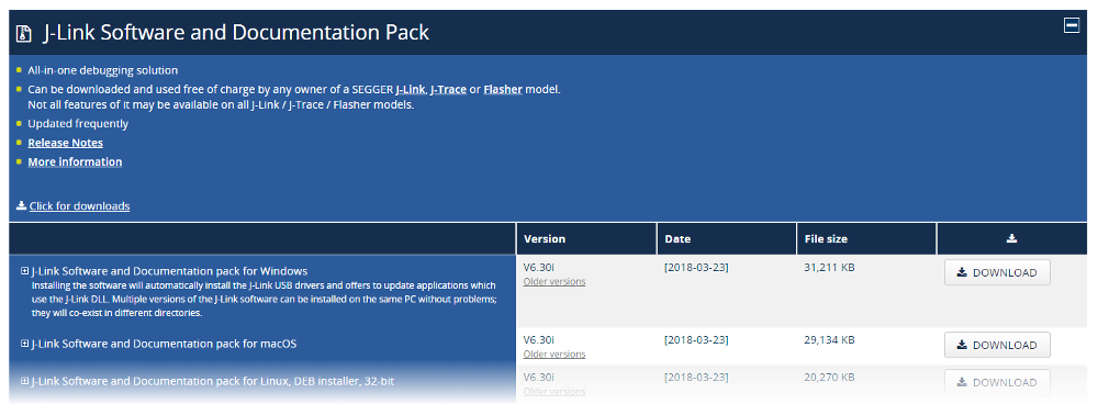
In order to use and program the Infineon XMC microcontrollers in the Arduino IDE, SEGGER J-Link must be installed on your PC. Please follow this link to SEGGER J-Link and install the J-Link Software and Documentation Pack for your operating system. If you have already installed 'DAVE™ - Development Platform for XMC™ Microcontrollers', you can skip this step as the respective drivers/programs are already installed on your system.

J-Link

Required tools

XMC-for-Arduino requires Python 3.x and pyserial. Make sure Python is installed in your machine and available in the system path. You can check if it was successfully installed by opening your command line or terminal and typing:

  python --version

With pip available, install the mentioned packages from a terminal:

  pip install pyserial

Using Arduino IDE

Preferences

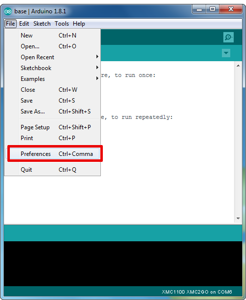
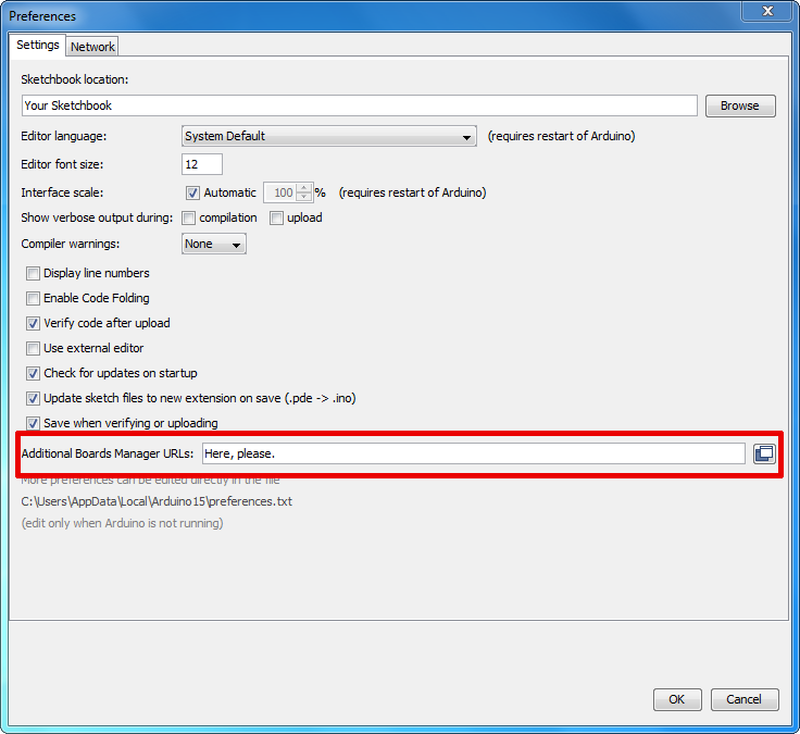
Paste the following URL into the 'Additional Boards Manager URLs' input field under File > Preferences to add Infineon's microcontroller boards to the Arduino IDE.

https://github.com/Infineon/XMC-for-Arduino/releases/latest/download/package_infineon_index.json

Easier to copy (no clickable link):

https://github.com/Infineon/XMC-for-Arduino/releases/latest/download/package_infineon_index.json

Adding a Board JSON

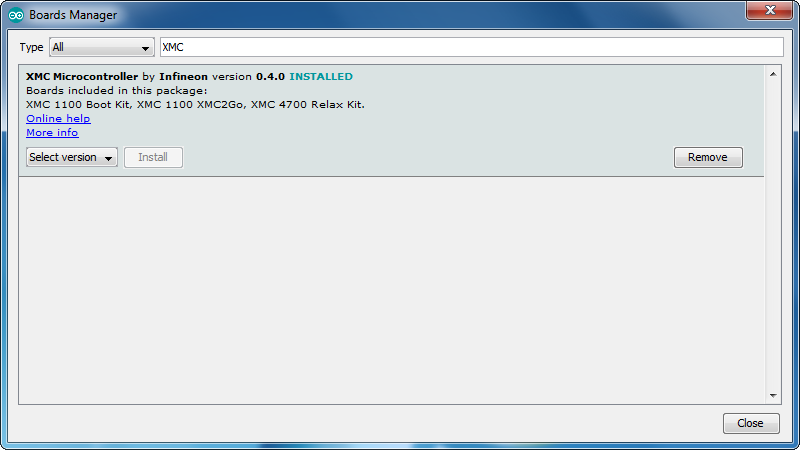
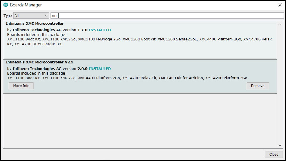
To install the boards, please navigate to Tools > Board > Boards Manager... and search for XMC. You will find options to install the board files for the microcontrollers. Click "Install" to add the boards to your Arduino IDE.

Infineon Board Entry

Note: For information on separation of release packages from version 2.0.0 onwards, see below.

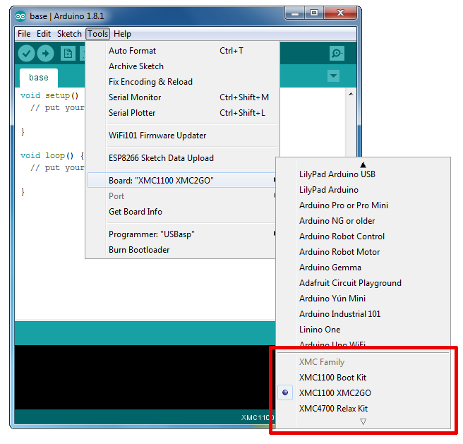
In the boards list Tools > Board, the XMC microcontroller boards are added and can be used from now on.

Board List

Important Notes

  • This integration will only work for Arduino IDE >=1.5
  • The XMC1100 Boot Kit has limitations if compared to the official Arduino boards (consult the XMC-for-Arduino Wiki for more information)
  • Refer also to the LICENSE.md/txt file for further information
  • Arduino 1.8.0 IDE might have problems with the XMC-for-Arduino releases
  • XMC-for-Arduino support for 'arm-linux-gnueabihf' only until version 1.1.

Separation of release packages from version 2.0.0 onwards

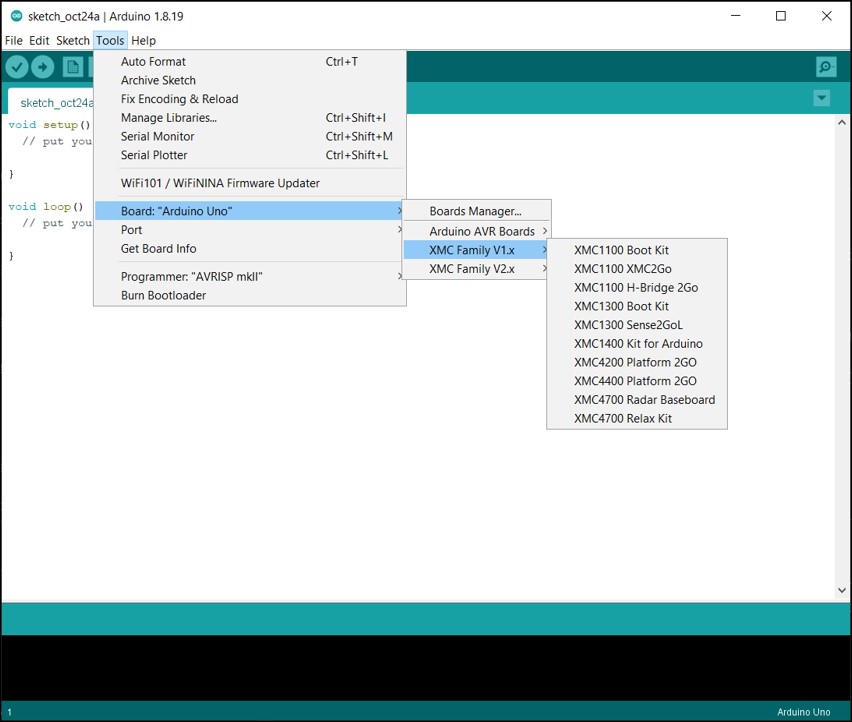
Certain obsolete boards (see wiki) and non-functional libraries were removed from the board support package for the release version 2.0.0, alongwith some other major changes (see release notes). However, in order to support legacy code, these removed boards/libraries are still available as a part of release version 1.7.0. Hence, the release packages have been split as shown in the pictures below.

Board Manager

The boards until version 1.7.0 have been clubbed under XMC Family V1.x.

Board list v1x

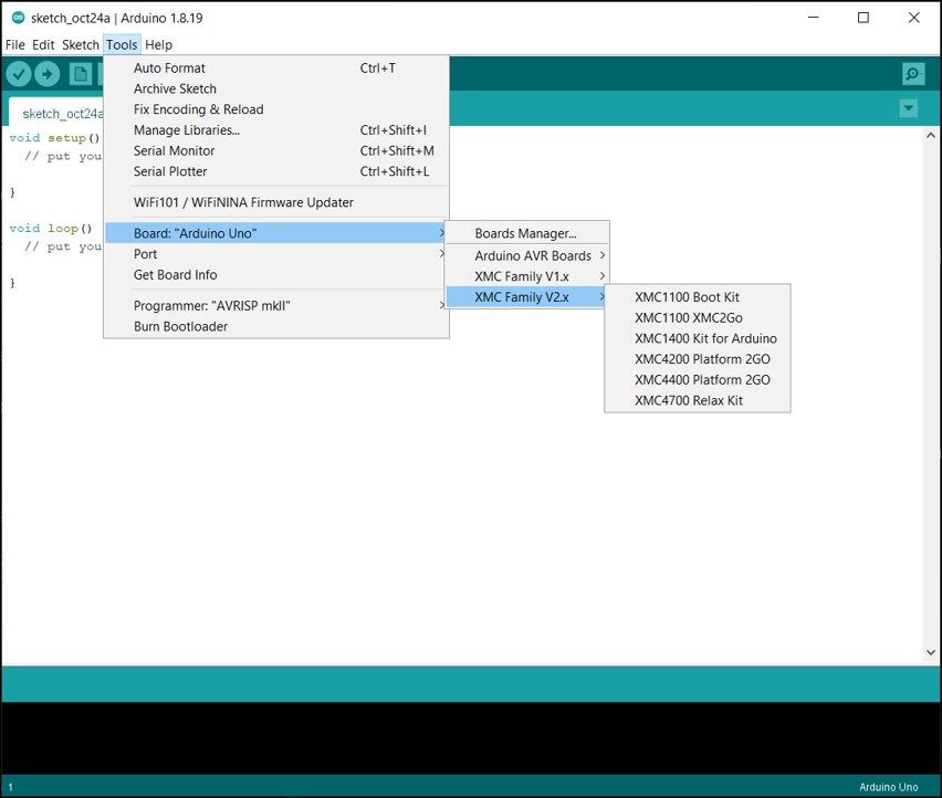
Any new board or feature integration will only be done in the XMC Family V2.x

Board list v1x

Known Issues

  • ⚠️ While using the pins connected to the LEDs configured as INPUT, there might be some abberation in behavior due to the presence of the series resistor of the LED, as it causes a voltage drop on the pin. In case of such an occurance, it is advised to desolder the series resistor and the LED and thereby using the pin as INPUT.

Using PlatformIO IDE

Contributing and Third Party Libraries

To contribute enhancements, fixes and the like see Contributors.md. in root folder

Third Party or external library maintainers see Libraries.md. in root folder

Also see Wiki for any additional information

Additional Contributors

xmc-for-arduino's People

Contributors

9volts9er avatar arkajyotichatterjee avatar boramonideep avatar danielstuart14 avatar djaumann avatar ederjc avatar ifx-anusha avatar ivankravets avatar jaenrig-ifx avatar linjingzhang avatar mhoechner avatar mhollfelder avatar mkiessling-ifx avatar mohamemu avatar mothesd avatar mtnmbr avatar olaffilies avatar pablopl avatar pandayswarnam avatar peterhuewe avatar pfeerick avatar rudolphriedel avatar sharmashubha avatar sherylll avatar techpaul avatar

Stargazers

 avatar  avatar  avatar  avatar  avatar  avatar  avatar  avatar  avatar  avatar  avatar  avatar  avatar  avatar  avatar  avatar  avatar  avatar  avatar  avatar  avatar  avatar  avatar  avatar  avatar  avatar  avatar  avatar  avatar  avatar  avatar  avatar  avatar  avatar  avatar  avatar  avatar  avatar  avatar  avatar  avatar  avatar  avatar  avatar  avatar  avatar  avatar  avatar  avatar  avatar  avatar  avatar  avatar  avatar  avatar  avatar  avatar  avatar  avatar  avatar  avatar  avatar  avatar  avatar  avatar  avatar  avatar  avatar  avatar  avatar  avatar  avatar  avatar  avatar  avatar  avatar  avatar  avatar  avatar  avatar  avatar  avatar  avatar  avatar  avatar  avatar  avatar  avatar  avatar  avatar  avatar  avatar  avatar  avatar  avatar  avatar  avatar  avatar  avatar

Watchers

 avatar  avatar  avatar  avatar  avatar  avatar  avatar  avatar  avatar  avatar  avatar  avatar  avatar  avatar  avatar  avatar  avatar  avatar  avatar  avatar  avatar  avatar  avatar  avatar  avatar  avatar  avatar  avatar  avatar  avatar  avatar  avatar  avatar  avatar  avatar

xmc-for-arduino's Issues

Additional Compiler error removal

One of the remianing compiler warning errors can be removed by conditional compiling out a function in xmc_vadc.c and xmc_vadc.h as follows

#if 0
/* API to Set the Global IClass registers*/
void XMC_VADC_GLOBAL_InputClassInit(XMC_VADC_GLOBAL_t *const global_ptr, const XMC_VADC_GLOBAL_CLASS_t config,
                                          const XMC_VADC_GROUP_CONV_t conv_type, const uint32_t set_num)

Basically the function for classifying External Mux for ADC is not used in any of the board support packages for XMC-for-Arduino.

At this stage permanently comenting out the function will have no adverse effect on your code as it is never called.

My next pull request will include this

Analog pins numbered wrong (compared to Arduino)

Started using ADC and got weird errors always 0

Eventually tracked down to pins_ardino.h where A0 is defined as Arduino pin 17

In Arduino you pass in Analog chennel number (same as analog pin) as being 0 to 'n' on most boards 0-7 on Mega 0-15. See reference for analogRead on https://www.arduino.cc/reference/en/language/functions/analog-io/analogread/

Temporary patch my loop is use analogRead( i + A0 ), this is not ideal.

Will look at adding a generalised pin mapping table to wiring_analog.c to be used by analogRead to convert pins and use AN0 etc for actual pins in pins_arduino.h

Currently seen on XMC110 Boot Kit will look at other boards at same time when doing patch. So patch will be for all supported boards.

Masses of compiler warnings on empty project

Using Arduino 1.8.5 and 1.0.1 as latest available from Board Manager

Standard test I do for any Arduino Board Package is

  1. Start with standard EMPTY project with empty setup and loop
  2. Set preferences -> Compiler Warnings to ALL
  3. Select new board
  4. Click verify (compile NO download)
  5. See if ANY warnings or errors come up
  6. If no errors repeat steps 3 to 5 for any other board in the board package

This checks for any hidden traps and that board package selection has no weird errors as well.

Ran on board XMC1100 and got MASSES of warnings some look like hidden traps in some circumstances, but should not be there. Examples

A) redefine true

../Application Data\Arduino15\packages\Infineon\hardware\arm\1.0.1\cores/wiring_constants.h:34:0: warning: "true" redefined [enabled by default]

#define true 1
../\Application Data\Arduino15\packages\Infineon\hardware\arm\1.0.1\cores/Arduino.h:31:0,
.../applic1\arduin1\packages\arduino\tools\arm-no2\480e151.3-2\lib\gcc\arm-none-eabi\4.8.3\include\stdbool.h:43:0: note: this is the location of the previous definition

#define true true

B) redfine false
In file included from C:.......\Application Data\Arduino15\packages\Infineon\hardware\arm\1.0.1\cores/Arduino.h:165:0,

             from C:\.....\Temp\arduino_build_342383\sketch\sketch_feb12a.ino.cpp:1:

C:......\Application Data\Arduino15\packages\Infineon\hardware\arm\1.0.1\cores/wiring_constants.h:35:0: warning: "false" redefined [enabled by default]

#define false 0

In file included from C:\Documents and Settings\Paul\Local Settings\Application Data\Arduino15\packages\Infineon\hardware\arm\1.0.1\cores/Arduino.h:31:0,

             from C:\.....\Temp\arduino_build_342383\sketch\sketch_feb12a.ino.cpp:1:

c:......\applic1\arduin1\packages\arduino\tools\arm-no2\480e151.3-2\lib\gcc\arm-none-eabi\4.8.3\include\stdbool.h:42:0: note: this is the location of the previous definition

#define false false

C) Defined but not declared functions
C:.....\Local Settings\Application Data\Arduino15\packages\Infineon\hardware\arm\1.0.1\cores/wiring_digital.h:74:24: warning: inline function 'digitalToggle' declared but never defined [enabled by default]

 extern inline void digitalToggle(uint8_t pin);

C:.....\Local Settings\Application Data\Arduino15\packages\Infineon\hardware\arm\1.0.1\cores/wiring_digital.h:67:27: warning: inline function 'digitalRead' declared but never defined [enabled by default]

 extern inline uint8_t digitalRead(uint8_t pin);

C:....\Local Settings\Application Data\Arduino15\packages\Infineon\hardware\arm\1.0.1\cores/wiring_digital.h:58:24: warning: inline function 'digitalWrite' declared but never defined [enabled by default]

 extern inline void digitalWrite(uint8_t pin, uint8_t val);

[Then repeated again]

D) Missing braces
C:.....\Local Settings\Application Data\Arduino15\packages\Infineon\hardware\arm\1.0.1\cores\wiring_analog.c:40:5: warning: missing braces around initializer [-Wmissing-braces]

 XMC_VADC_GLOBAL_CONFIG_t vadc_global_config = {0};

Many other types of error and then repeats at link stage something like 60 warnings/errors listed.

Is there a contact I can talk details with

Rather than fill here up with questions is there somebody there I can directly contact at least by email?
NOT a general support or general contact email, and go through hoops to find right person.

My email is shown on my profile.

In tidying up getiing memory sizes and improving safety on stack usage I have come across issues like

  1. For XMC4 series you allocate special areas of memory for chip id and copy the WRONG data to it!! In system_XMC_4700.c (and for XMC_4800) as part of the initialisation 16 bytes of memory are copied from the bottom of USB_RAM (DSRAM_1_system = 0x20000000) to top of DSRAM_2_comm at 0x2003ffc4, None of these areas are the SCU IDCHIP register. Then I can find NO reference to anything using the values after that anywhere.

  2. SystemCoreClock is forced to special locations on platforms for no apparent reason. Especially as on XMC1 series it could be put into the bottom 12 bytes of SRAM that are not used for anything else. I actually think that as it appears to be always used by name, it could be a standard variable in data or bss sections.

  3. Stack on XMC4 series is dangerously at bottom of Programme RAM (PSRAM) so in event of stack overflow you will go off into never never land. If it was top of PSRAM and you were actually using Stack limit hardware functions one could recover and get a stack trace

  4. XMC4 series appears to be using combined RAM as one large chunk with a gap in the middle with some of the higher areas at times used for USB and Ethernet.

There are other issues that come up and use up time locating where things are used.

Information new compiler Warning on startup_XMC4700.S

Using V1.1.1 and board XMC4700, with ALL Warnings, means compiler version change produces a warning in

startup_XMC4700.S

Warning messages are

IT blocks containing more than one conditional instruction are deprecated in ARMv8

On lines

....\Arduino15\packages\Infineon\hardware\arm\1.1.1\variants\XMC4700\startup_XMC4700.S:241:

.....\Arduino15\packages\Infineon\hardware\arm\1.1.1\variants\XMC4700\startup_XMC4700.S:272:

The code blocks are

.L_loop0_0:
	subs	r3, #4
	ittt	ge
	ldrge	r0, [r1, r3]
	strge	r0, [r2, r3]   <----- line 241
	bge	.L_loop0_0

and

.L_loop2_0:
	subs	r2, #4
	itt	ge
	strge	r0, [r1, r2]  <----- line 272
	bge	.L_loop2_0

At this stage it can be ignored, as this is a performance warning that is not relevant at that point in the code.

Interrupt input pin is high ohmic after startup, but activates pull down on first interrupt

Affected product: XMC4700 Relax kit
Expected behavior: Internal pull down of an input pin can be configured or at least stays constant (as seen on Arduino Mega)
Seen behavior: Internal pull down setting changes if an interrupt is received (seen on XMC4700 Relax Kit)

Reproduce:

Consider this demo code from the arduino IDE which waits (attaches an interrupt) on a signal change on pin2 and changes output signal on pin 7 accordingly.

const byte firePin = 7;
const byte interruptPin = 2;
volatile byte state = LOW;

void setup() {
  pinMode(firePin, OUTPUT);
  pinMode(interruptPin, INPUT);
  attachInterrupt(digitalPinToInterrupt(interruptPin), blink, CHANGE );
}

void loop() {
  digitalWrite(firePin, state);
}

void blink() {
  state = !state;
}

If you observe this on the oscilloscope after boot up, you can see (yellow signal), that the input signal is around 5V. This signal is supplied by an pull up of an attached sensor (pull up to 5V via 1.2kOhm). The XMC kit is configured to wait on a signal change on pin 2. Once the interrupt occurs, it is recognized and accordingly an output pin is set (pin 7, blue).

Then the sensor tries to go back to high signal, 5V but fails to do, since the XMC Relax kit has reconfigured the input pin, now activating its internal pull down (which is now in conflict with the pull up of the sensor). The sensor is only able to go up to ~2.5V, so the second change is not recognized anymore by the interrupt

Can the input pin configured high-impedance state, no pull down?

grafik

The same code running on an Arduino Mega with the same sensor setup shows that on this plattform the pull down is not activated and thus the sensor is able to reach up again to 5V.

grafik

Problem using XMC for Arduino in Ubuntu 16.04

I set up a new system with a distro based on ubuntu 16.04.
I have installed everything in 64bit(tripple checked).
but when i try to upload the software to the MCU i get following errormessage:

BridJ: dlopen error when loading /opt/SEGGER/JLink_V632e/libjlinkarm_x86.so.6.32.5 : /opt/SEGGER/JLink_V632e/libjlinkarm_x86.so.6.32.5: wrong ELF-Class: ELFCLASS32

Exception in thread "main" java.lang.UnsatisfiedLinkError: jlinkarm.JLinkARMLibrary.JLINKARM_GetDLLVersion()I
at jlinkarm.JLinkARMLibrary.JLINKARM_GetDLLVersion(Native Method)
at Infineon.JLinkDebugger.GetDLLVersion(Unknown Source)
at Infineon.XMCDevice.Program(Unknown Source)
at Infineon.upload.main(Unknown Source)

Since starting the jlink-console from terminal works I don't think it's a problem on seggers site, but these are just my 2 ct.

Support for other boards / mcu's

Is there a plan to add other boards for example XMC1400 Boot Kit ?

I intend to use XMC1403 or XMC1404 for a new projekt with CAN/LIN communication and it would be very helpfull for rapid prototyping .

Best regards
Hubert

New Wiki errors XMC1100 H Bridge 2 Go page

In key features says can be powered by 3V3.

Manual for the board says external 5V (to save the on board regulator) they actually suggest using board pin 29 for +5V and 28 and/or 27 for GND.

In last paragraph there are mentions of XMC2Go and H bridge in last sentence

I would suggest change "XMC2Go" to "H-Bridge 2Go"

Also last "H bridge" to "H bridge chip"

Will check through other parts later

serialEvent() not working on XMC 4700

I tried to implement an Serial Event Handler (https://www.arduino.cc/en/Tutorial/SerialEvent)

Expected behavior:
XMC shall write back "Hello!" on the console if a Serial input is given.
Seen behavior:
Noting happens.

The XMC implementation does not call serialEvent from a sketch.
The HardwareSerial.cpp (https://github.com/Infineon/XMC-for-Arduino/blob/c38915f4cb1691a5ad3e64e9bd12e76040510cde/arm/cores/HardwareSerial.cpp) does not implement a call of its function void serialEventRun(void) from line 32.
I guess somewhere further below (in void HardwareSerial::IrqHandler ?) there is a missing call of serialEventRun(). I guess the root cause is located in HardwareSerial.cpp

Consider the following code
`
void setup() {
// put your setup code here, to run once:
Serial.begin(250000);
}

void loop() {
// put your main code here, to run repeatedly:
delay(1000);
}

void serialEvent()
{
Serial.println("Hello!");
}
`

PHPoC WiFi Shield connection with XMC 1100 bootkit

Hi there,

PHPoC WiFi Shield for Arduino connects it to WiFi networks. Since, XMC 1100 boot kit has same form factor as of Arduino and almost similar pin out diagram, can PHPoC WiFi Shield be used with XMC 1100 boot kit?
Similarly, can Infineon's High Side Switch Shield with BTS50015-1TAD for Arduino be used with XMC 1100 BOOT KIT?
Or for that matter, can shields for Arduino Uno be used with XMC 1100 boot kit?

Poor Linux support for XMC2Go

On F25, figured the config doesn't work with the F25 packaged Arduino 1.6.4. Required upgrade to Arduino 1.8 to get it to find the compiler.
Then, JLink rpm installs to /opt which is not in the library path, hence uploading to the board doesn't work. Need to tweak the environment variable.
Finally, JLink couldn't connect to the board. Tried on another PC with Windows -> the board works.

That's where I deinstalled everything and went back to Arduino boards which work out of the box. Too much trouble debugging a tool chain...

SPI works very slow with OLED-Display and u8g2 library

I made some test with I2C (SH1106) and SPI (SSD1309) with 128x64 OLED displays using u8g2 library, and compared with 2 other Boards ( Teensy 3.2 and TeensyLC ) i have here.
While I2C deliveres more or less the same result for filling the screen on all plattforns -> 1kB needs about 33ms to be sent to the Display on 400000Hz, i found that SPI workes much to slow .
on the XMC1404 it takes more then 60ms and on the XMC2Go more than 200ms, while on the teensy boards it is only 2,7ms ( Teensy 3.2@ 48MHz ) and 3,5 ms (TeensyLC@48MHz) .
I will do some more test with XMC1300 and XMC4700 boards.

best regards

Hubert

Problem with Update to v1.1.1

Hi!

ArduinoIDE tells me there is a new Version but it won't let me install/download it.

Fehler beim Herunterladen von https://github.com/Infineon/XMC-for-Arduino/releases/download/V1.1.1/XMC_IFX_1.1.1.zip
java.lang.RuntimeException: java.lang.Exception: Fehler beim Herunterladen von https://github.com/Infineon/XMC-for-Arduino/releases/download/V1.1.1/XMC_IFX_1.1.1.zip
at cc.arduino.contributions.packages.ui.ContributionManagerUI.lambda$onInstallPressed$1(ContributionManagerUI.java:176)
at java.lang.Thread.run(Thread.java:748)
Caused by: java.lang.Exception: Fehler beim Herunterladen von https://github.com/Infineon/XMC-for-Arduino/releases/download/V1.1.1/XMC_IFX_1.1.1.zip
at cc.arduino.contributions.DownloadableContributionsDownloader.download(DownloadableContributionsDownloader.java:131)
at cc.arduino.contributions.DownloadableContributionsDownloader.download(DownloadableContributionsDownloader.java:69)
at cc.arduino.contributions.packages.ContributionInstaller.install(ContributionInstaller.java:102)
at cc.arduino.contributions.packages.ui.ContributionManagerUI.lambda$onInstallPressed$1(ContributionManagerUI.java:173)
... 1 more
Caused by: java.io.IOException: Received invalid http status code from server: 416
at cc.arduino.utils.network.FileDownloader.downloadFile(FileDownloader.java:194)
at cc.arduino.utils.network.FileDownloader.download(FileDownloader.java:128)
at cc.arduino.contributions.DownloadableContributionsDownloader.download(DownloadableContributionsDownloader.java:129)
... 4 more

Objcopy gives WRONG size for code and Flash usage

I was playing around with checks on defines and memory usage from linker and noted the figures given by objcopy at end of Arduino compilation are WIDELY wrong.

With Following program (you will need to add __stack_start to linker file) I get compile size indication of
testdefines.zip

"Sketch uses 4444 bytes (6%) of program storage space. Maximum is 65536 bytes."

However the output I get is

PC Services - XMC-for-Arduino useful defines example

Family		(1)
Series		(11)
Device		(1100)
Package		(7)
Flash (kB)	64
Library Version	2.1.8

Memory usage-
Code Size:	1112
Veneer:		68
Stack		512
Data		47
Ram Code  	0
bss		163
Heap		3301

Total Flash	1227
Ram less heap	210

Firstly unless objcopy is including heap there is no way to get to 4444 bytes in FLASH, obviously objcopy is including in the 65526 (Flash size of XMC1100 Boot Kit) areas that are in RAM and uninitialised. So this can give confusing results that will claim large programs are larger than the Flash size as it is including large amounts of uninitialised data from RAM.

XMC 4700 Pin Out

Hey Manuel,
it seem to be a pin out mismatch at XMC 4700 (pins_arduino.h)!

#define A0 17 (at the picture Arduino pin 22)
#define A1 18 (at the picture Arduino pin 21)
#define A2 19 (at the picture Arduino pin 20)
#define A3 20 (at the picture Arduino pin 19)
#define A4 21 (at the picture Arduino pin 18)
#define A5 22 (at the picture Arduino pin 17)

Regards Andreas

Support for the XMC4500 Relax

Dear Infineon engineers,

thanks a lot for giving out a XMC Boardspackage for Arduino!
Could you please add the XMC4500 Relax and XMC4500 Relax Lite series as well? I would love to experiment with this boards - from this new perspective.

Thanks a lot for your great work 👍

Troubles with I2C Communication between Boot Kit 1100 and XMC2Go

Hi,

i wrote two sketches (see attachments) that should demonstrate a "plug-and-play" feature for i2c. While coding the example, I used an Arduino UNO and an XMC2Go. The Node_Demo.ino was flashed to the Arduino UNO, the Device_Demo was flashed to the XMC2Go. The communication between the two devices can be seen in the attached serial monitor screenshot. I then swapped out the Arduino UNO for a Boot Kit 1100. The code wasn't altered in any way. Still, the output that can be observed in the serial monitor changed. The communication always gets stuck early on. Could somebody please review my code and let me know, what triggers this different reaction of the Boot Kit compared to the Arduino.

arduino uno serial monitor
boot kit 1100 serial monitor

I2C_PlugNPlay.zip

Comments required on RTC library and examples

I am currently looking at changing (drastically) RTC library as it has many bugs in it, most noatbly Alarm functions can only be on same day or same time as RTC, as changing any parameters resets other parameters to current RTC values.

Already improved XMCLIB lower level of xmc_rtc to deprecate the alarm structure definition and use the time definition, this reduces code size and code complexity.

Current plan to change API to use structures for date and time with

  • Formats as XMC time and Standard tm format
  • Conversion routines to convert between both types
  • User defines where and what name to call time structures
  • Less functions that pass in the address of a structure using XMC time format
  • User modifies the relevant parts of structures, between calls
  • Extra functions
    • From Build of RTC.cpp using 4 digit year date get the build date and time into a time structure. Note on most systems closing Arduino IDE and reopening forces a rebuild of library (or changing board and back again)
    • From a 4 digit year date format create correct day of week

This will reduce code and RAM wastage in the library and be more usable

Important questions

  1. Iis anybody really insistent on using the buggy API as it is?
  2. Would losing myriads of calls to get/set single members of the time structure be a great loss
  3. Would having ability to set alarm at different time or date from now be helpful

Documentation Required (Wiki) XMC 1300 Pin Out

Hi,

this project is very promising as it makes transitioning a lot easier.
I just upgraded to xmc 1300, since I have seen it in the Arduino IDE as supported Board.

Now I was wondering that the PinOut for the xmc1300 in terms of Arduino pins is.
I did not find any docs in this regard - can we have a picture like we have one for XMC1300.
Or am I missing something and there was a way to map this from the XMC1100 board?

Also if xmc1300 really works this should really be documented here since that is amazing.

Thanks a lot !!!!

I2C Wire.begin() non-blocking issue - XMC1100 + TLE94112LE

After the last 1.0.4 Arduino IDE library update by @mhollfelder everything is working fine with the I2C bus. Tested with a Raspberry Pi Compute Module 3 on a multiple I2C peripheral bus it works like a charm.

Problems arises when the XMC1100 Boot Kit is integrated with the TLE941120 DC motor controller. In the Setup() function there is different behaviour depending on where the Wire.begin() call is placed. In detail I have setup a use-case easy to reproduce:

To check the presence of the XMC1100 board on the I2C bus from the Linux terminal I used the command

i2cdetect -y 1

Wrong case

#include <Wire.h>
#include <Streaming.h>
#include <TLE94112.h>
[...]

//! I2C Slave address. 
#define SLAVE_ADDRESS 0x04
//! Motor control class instance
MotorControl motor;
[...]

// ==============================================
// Initialisation
// ==============================================
void setup() {
  // Serial is initialised at high speed.
  Serial.begin(38400);

  // Initialize i2c as slave
  Wire.begin(SLAVE_ADDRESS);

  // define callbacks for i2c communication
  Wire.onReceive(i2cReceiveData);
  Wire.onRequest(i2cSendData);

  // >>>>>>>>>>>> TLE LIBRARY INITIALISED AFTER THE I2C BUS <<<<<<<<<<<<<<
  // initialize the motor class
  motor.begin();  
}

Working case

#include <Wire.h>
#include <Streaming.h>
#include <TLE94112.h>
[...]

//! I2C Slave address. 
#define SLAVE_ADDRESS 0x04
//! Motor control class instance
MotorControl motor;
[...]

// ==============================================
// Initialisation
// ==============================================
void setup() {
  // Serial is initialised at high speed.
  Serial.begin(38400);

  // >>>>>>>>>>>> TLE LIBRARY INITIALISED BEFORE THE I2C BUS <<<<<<<<<<<<<<
  // initialize the motor class
  motor.begin();  

  // Initialize i2c as slave
  Wire.begin(SLAVE_ADDRESS);

  // define callbacks for i2c communication
  Wire.onReceive(i2cReceiveData);
  Wire.onRequest(i2cSendData);
}

DeviceControl Issues and warning of change

Whilst doing first phase testing and updates on RTC library and examples, I foun that the DeviceControl examples (Sleep modes and Hibernate) have major issues of NOT doing what they say they are doing.

The configure Sleep mode for XMC1 and XMC4 series do not work properly and could cause strange effects, there are BIG warnings in the User Manuals for the devices about powering down or clock gating peripherals in Sleep Mode like

Note: Swiching off amodule clock during operation may result in unecpected effects
like e.g. clock spikes or protocol violations. Before entering Sleep mode the affected
modules should be in reset state. After retoration of the clocks the modules need
to be re-initialized in order to ensure proper function.

So before entering sleep or deep sleep or hibernate mode all peripheral;s should be in reset state, then when an interupt occurs the peripherals required need to be re-initialised.

None of which is in the code or realistically could be added to the Arduino style framework.

On XMC1 series attempts to gate clocks to modules was done wrong and to protected registers so had NO effect and was leaving all peripherals on anyway .

DeviceControl will be changed to

  1. Have Sleep/Deep Sleep or Hibernate modes for CPU ONLY (Deep sleep is CPU and Flash in Sleep Mode.
  2. Hibernate mode on XMC4 series will be tested later this week when I have a board to test it on.
  3. All peripherals and clocks will be ON to enable an interrupt from ANY to wake up CPU.
  4. Sleep and hiberanate examples will be under DeviceControl not RTC, even though they us the RTC.

Later this week there will be a pull request once the examples and code has been tested on a few boards.

Tx and Rx pin for UART in XMC 2GO

As shown in the attached image:
XMC 2Go_PO

the UART Rx and Tx pin mentioned are P2.6 and P2.0 respectively. However, in the user manual released by Infineon, the UART Rx and Tx pins mentioned are P2.1 and P2.2. Please find the user manual attached herewith (on page 11 of 15):

Board_Users_Manual_XMC_2Go_Kit_with_XMC1100_R1.0.pdf

Which one is correct? I think the one in the user manual is the right one.

Serial and systick events handling

Whilst double and triiple checking previous patches I discovered a couple of bugs, also I was trying to track down the serial transmit issues, when using simple test code

#include <Arduino.h>

extern uint8_t tone_pins[ NUM_TONE_PINS ];
extern uint8_t tone_irq[ NUM_TONE_PINS ];
extern uint32_t timer_ids[ NUM_TONE_PINS ];
extern volatile long timer_toggle_count[ NUM_TONE_PINS ];

void setup()
{
Serial.begin( 115200 );
//tone( LED1, 1 );
//tone( LED2, 4, 10000 );
//tone( LED5, 10, 5000 );
//tone( LED6, 20, 3000 );
delay( 45 );
Serial.println( "pin\tirq\tid\tCount" );
for( int i = 0; i < NUM_TONE_PINS; i++ )
  {
  Serial.print( tone_pins[ i ] );
  Serial.print( "\t" );
  Serial.print( tone_irq[ i ] );
  Serial.print( "\t" );
  Serial.print( timer_ids[ i ] );
  Serial.print( "\t" );
  Serial.println( timer_toggle_count[ i ] );
  }
}

void loop() {
}

First problem unless there is about 45 ms delay between Serial.begin and the first Serial.print or serial .write, no serial output occurs.

Second problem if multiple systick events are setup, which are only done for delay and tone functions, only the last is actioned until complete, then the next until completion. So a continuous tone output stops many other things happening like delay().

Basically Systick handlers doing scheduling of tasks has so many pointers and lack of correct scanning of linked lists that it only processes the last event, not the whole list. This has obviously only been tested with one event in play at any time. there are countless other issues with what should be volatile and less bloat as the maximum events being handled is known at compile time, so does not need linked list but fixed array with enable flags.

Next stage as soon as I get some time is to port some of my own scheduling code that is known to work to replace the linked list fiasco. Also I will see about making RX as well as TX using the FULL 32 word FIFO to allow the hardware to complete whilst interrupts are turned off for delaymicroseconds and no doubt other places. All things Systick related will use milli seconds as minimum resolution as 1 ms is the smallest increment possible anyway.

On >16 MHz processors and lots of I/O 4 tone pins is adequate, whilst on >100 MHz processors 16 tone pins should be possible easily.

Once I get a stage that is working well for systick events at 1 kHz and allow for different numbers of tone outputs on different platforms I will probably tag a level of my fork of the repository as V1.06a.

Hopefully I might stumble across the serial issues as well as a better way to do hardware based delaymicroseconds.

There will probably be a wiki on my repository and/or page on my website as well

XMC1300 Bootkit in commits

Hi, I saw that there is a variant for the XMC1300 Boot Kit but it does't appear in the latest release as the README indicates.

Is there a way for me to include the board into Arduino manually? Thank you!

XMC 2GO H-Bridge

Hi All,
I tried more example code especially IFX9201 motor control but it is not working.
Does not work at all or do I have the problem?

Thank You!

Attila

Version 1.1.0 breaks Serial.available()

Since version 1.1.0 Serial.available() will always return 0.

After updating my code stopped working. I figured out that Serial.available() causes the problems since it won't return something != 0.

The following code will never send 'a':

#define PIN 0x0e
//#define PIN 0x0f

void setup() {
  Serial.begin(115200);
  // put your setup code here, to run once:
  pinMode(PIN, OUTPUT);
}

void loop() {
  // put your main code here, to run repeatedly:
  digitalWrite(PIN, HIGH);
  delay(500);
  digitalWrite(PIN, LOW);
  delay(500);

  if (Serial.available())
    Serial.write('a');
  else
    Serial.write('b');
}

Downgrading to 1.0.6 makes it work again and upgrading to 1.1.0 breaks it again.

Transmit interrupt stops at random times

Have program building up, no external hardware connected so no interference from base XMC100 Boot Kit.

Currently stages of code can be seen from reading random analog values (fine for now will change with hardware attached,) some serial output and controlling of GPIO outputs and delay calls to simplify things for the moment.

When running with serial (to debugger), GPIO mainly outputs for external and board LEDs and delays works fine and can see LEDs on board changing at 1 second delay intervals as expected and messages as expected.

Adding of analogRead causes random time when transmit interrupt stops, then programme eventually gets to spin lock waiting for buffer to empty. This I can tell because the serial output stops appearing at a random time, but other program steps (changes in LEDs and GPIOs carry on for a while, then LED changes stop showing stuck waiting for serial to catch up.

Comment out the ONE line in a loop that does analogRead and this lock up does not occur

// Scan and total on each channel
for( j = 0; j < ADC_AVG_DEPTH; j++ )
   for( i = 0; i <= max; i++ )
     /* adc_readings[ i ] += analogRead( i + A0 )*/;
// Create average
for( i = 0; i <= max; i++ )
   adc_readings[ i ] /= ADC_AVG_DEPTH;

So nothing complex, in perfoming 4 scans of 2 channels, then after averaging.

There is some interaction with these types of operation which means transmit interrupt gets missed, or stopped. Not had time to track down further.

Function micros() is not working properly

Hi, i have some issues by running some code on the XMC 2Go.
One of the issue is that the function micros() is not working properly.
It returns only milliseconds as smallest value.
The microseconds are always zero.

Here small code example:
`
unsigned long s1 = 0;
unsigned long s2 = 0;

void setup() {
Serial.begin(115200);
}

void loop() {
s2 = s1;
s1 = micros();
Serial.print(s1);
Serial.print('\t');
Serial.println(s1 - s2);
delayMicroseconds(1);
}
`

9945000 2000
9946000 1000
9947000 1000
9948000 1000
9949000 1000
9951000 2000
9952000 1000
9953000 1000
9954000 1000
9955000 1000
9957000 2000
9958000 1000
9959000 1000
9960000 1000
9962000 2000
9963000 1000
9964000 1000
9965000 1000
9966000 1000
9968000 2000
9969000 1000

wiring_time module excessive functions and delaymicroseconds

Wiring_time includes all sorts of event timerlist as a linked list with all the insert/delete and other management. However the only use of it appears to be for delay function for millisecond delay.

With lots of handler linked list timer objects being accessed as functions and from handlers suggesting more objects should be actually volatiles.

Personally all the code for linked list management, could be better replaced by a fixed array with known offsets set at compile time for all possible systick timer events, and probably find there is only ONE.

Delaymicroseconds while inlined with NOP loops is only useful for at most a 10 microsecond delay beyond that it disables interrupts that can really mess things up. I have times where 100 to 200 microsecond delays are needed.

A 10 microsecond delay means for XMC1xxxx at 32 MHz we use 320 clock cycles or 160 NOPs .
Whilst on XMC4xxx this is 1440 clock cycles and 1470 NOPs

Realistically if there is a timer/events map for what XMC-for-Arduino uses it could do with a hardware timer delay and interrupt for > 10 microsecond delay on XMC1xxx, and use this method only for XMC4xxx

Setting up HardwareSerial and or implementing SoftwareSerial

Hi there,

I have been testing some of my arduino projects with an XMC 1300.
The project port very well, so thanks a lot for setting up this project.

I found that some arduino libraries use a SoftwareSerial as a parameter.
Would we have to implement Software Serial to use such libraries like bportaluri/WiFiEsp?

WiFi.init(&MyCustomSoftwareSerial); // the init takes a &Stream as parameter

If HardwareSerial is a Stream I guess I could pass that, yet how to set it up?
Or SoftwareSerial adruino lib only seems to be missing interrupt.h how could I set one of those up?

Regards
Sim

XMC1100 Serial class problem

I stumbled across a subtle problem in the HardwareSerial class whereby a receive character can get caught in the USIC buffer. Since we only get an interrupt on change of state and currently the HardwareSerial class only reads one character from the USIC, one character can remain queued. This tends to show itself when debugging and you hit a breakpoint, then restart the code with serial data coming in. My solution was the following code in the HardwareSerial.cpp isr:
XMC_UART_CH_ClearStatusFlag(_XMC_UART_config->channel, (XMC_UART_CH_STATUS_FLAG_ALTERNATIVE_RECEIVE_INDICATION | XMC_UART_CH_STATUS_FLAG_RECEIVE_INDICATION)); while(_XMC_UART_config->channel->RBUFSR & (USIC_CH_RBUFSR_RDV0_Msk | USIC_CH_RBUFSR_RDV1_Msk)) { _rx_buffer->store_char(XMC_UART_CH_GetReceivedData(_XMC_UART_config->channel)); }

Program erased on power down?

I have a 3D magnetic sensor to go kit (TLE493D A2B6) and can program it fine using the "XMC1100 XMC2Go" board. Once I remove power, and reapply power, it seems that the memory is erased. At least, the previously programmed sketch does not run. How can I permanently program my sketch into the memory so it runs on power up? (I'm comfortable using the J-Link Commander if that will solve my issue). Thanks in advance!

i2c issues on XMC2GO

I've connected ssd1306 oled display over i2c to xmc2go.

I've tried to run program from https://playground.arduino.cc/Main/I2cScanner, but it's reporting that there is device connected over i2c, at (almost) every possible address

Scanning...
I2C device found at address 0x01  !
I2C device found at address 0x08  !
I2C device found at address 0x10  !
I2C device found at address 0x19  !
I2C device found at address 0x1F  !
I2C device found at address 0x29  !
I2C device found at address 0x2E  !
I2C device found at address 0x37  !
I2C device found at address 0x3C  !
I2C device found at address 0x44  !
I2C device found at address 0x48  !
I2C device found at address 0x50  !
I2C device found at address 0x53  !
I2C device found at address 0x5A  !
I2C device found at address 0x64  !
I2C device found at address 0x6E  !

After adding Wire.write(1) in loop, so it looks like

Wire.beginTransmission(address);
Wire.write(1);
error = Wire.endTransmission();

It works fine

Scanning...
I2C device found at address 0x3C  !
done

Second issue is that when I've conected ssd1306 display over i2c do xmc2go, with following code
https://gist.github.com/PabloPL/606615c00ef39bfd6b00c42a4db17ddb
(needs https://github.com/adafruit/Adafruit-GFX-Library and https://github.com/adafruit/Adafruit_SSD1306) it's running fine till reset/power down of board.
After power down and power up, app is blinkin leds correctly (so it's running), but lcd is not displaying anything.
I need to flash again this code to device and then it's working fine (till next power down/reset).

I'm using platform.io with https://github.com/Infineon/platformio-infineonxmc

Error downloading Infineon .json url in Arduino IDE

Has anyone programmed XMC microcontroller by Infineon Technologies using Arduino IDE?

I tried as per the steps given in the GitHub repo of Infineon. Below is the link of the same:

https://github.com/Infineon/XMC-for-Arduino/wiki/Implementation-in-Arduino-IDE

After I copied the .json url in the preferences, I am getting following error:

http://downloads.arduino.cc/packages/package_index.json file signature verification failed. File ignored.

Index error: could not find referenced tool name=arm-none-eabi-gcc version=4.8.3-2014q1 packager=arduino

What can be a possible solution for it? I am running Arduino IDE 1.8.5 on Windows 10. Is this has anything to do with it?

Problem with examples

I tried to compile several examples but they don't work. I am using the Arduino IDE version 1.8.5 and XMC 4700 board. Examples not compiling are: BGT24LTR11/print_motion, BGT24LTR11/print_raw_data, IFX9201 H-Bridge/MotorControl, RTC/HibernateRTC, SPI/BarometricPressureSensor, SPI/DigitalPotControl, Wire/digital_potentiometer, Wire/master_reader, Wire/master_writer, Wire/SFRRanger_reader, Wire/slave_receiver, Wire/slave_sender.
For example: in example HibernateRTC there is just no XMC_DeviceControl.h directory.

analogRead() not working for XMC 2Go

Hi,

The following code is not working in XMC 2Go. Could you please test on your side?

`void setup() {
// put your setup code here, to run once:
Serial.begin(9600);
// analogReadResolution(10);
// wiring_analog_init();
}

void loop() {
// put your main code here, to run repeatedly:
int sensor = analogRead(0);
Serial.println(sensor);
delay(3000);
}`

USB and onboard serial XMC2GO

Althougt it says so in the wiki page of the XMC2GO, by default there is only serial, which is the usb serial, and no serial1. I already found out, that the onboard serial is somehow disabled in this core file, but i couldn't get it to work.

Unable to flash sketch to XMC2GO on Linux

Board: XMC2GO
OS: Ubuntu 17.04
Arduino IDE: 1.8.5 (fresh download)
Arduino IDE XMC addon: 1.0.6

Tested using arduino blink sketch, and i'm not able to flash sketch using Arduino IDE (i'm able to do this using ozone from segger).

From IDE log i only see

Picked up JAVA_TOOL_OPTIONS: 
--------------------------
Infineon XMC Flasher Lite
Copyright Infineon Technologies 2017
--------------------------
Linux
Operating System: Linux

Initialisation
--------------------------
Linux

ls /opt/SEGGER/ is returning

lrwxrwxrwx 1 root root   23 paź  6 17:07 JLink -> /opt/SEGGER/JLink_V620e
drwxr-xr-x 8 root root 4096 paź 13 18:07 JLink_V620e
drwxr-xr-x 3 root root 4096 lis 10 14:25 ozone

SD.open() not returning File object

Hi,

I am testing example program (Datalogger.ino). The file is created but the function is not returning the object. Thus, I couldn't write or read to the file. I am using XMC 2Go.

Best regards,

`#include <SPI.h>
#include <SD.h>

const int chipSelect = 3;
SdFile root;

void setup() {
// Open serial communications and wait for port to open:
Serial.begin(9600);
while (!Serial) {
; // wait for serial port to connect. Needed for native USB port only
}

Serial.print("Initializing SD card...");

// see if the card is present and can be initialized:
if (!SD.begin(chipSelect)) {
Serial.println("Card failed, or not present");
// don't do anything more:
return;
}
Serial.println("card initialized.");
}

void loop() {
// make a string for assembling the data to log:
String dataString = "";

int sensor = analogRead(12);
dataString += String(sensor);
Serial.println(sensor);

// open the file. note that only one file can be open at a time,
// so you have to close this one before opening another.
File dataFile = SD.open("datalog2.txt", FILE_WRITE);

Serial.println(dataFile);

// if the file is available, write to it:
if (dataFile) {
dataFile.println(dataString);
dataFile.close();
// print to the serial port too:
Serial.println(dataString);
}
if the file isn't open, pop up an error:
else {
Serial.println("error opening datalog.txt");
}
delay(3000);

}
`

Suggestion on wiki

I have now created a wiki with my notes and what I am currently working on.

These notes maybe helpful to others and you might want to add link to it on your wiki

Techpaul Wiki

Compiler error when using Visual Micro/Atmel Studio7

Working perfect in Arduino IDE, but when compiling in Visual Micro/Atmel Studio7 the following Error occurs:

`Compiling`` 'Sketch1' for 'XMC1100 Boot Kit'
arm-none-eabi-g++*: warning: -x c++ after last input file has no effect

arm-none-eabi-g++*: fatal error: no input files
compilation terminated
Build failed for project 'Sketch1'`

issue with Ardino 1.8.5 and XMC1 Family and SPI and I2C C and CPP compatibility issue compilation error

initialization of XMC_GPIO_CONFIG_t with XMC1 Family
around line 130ish in HW_SPI.cpp SPIClass::end()

if((XMC_SPI_config->channel->CCR & USIC_CH_CCR_MODE_Msk) == XMC_USIC_CH_OPERATING_MODE_SPI)
{
    XMC_GPIO_CONFIG_t default_input_port_config = {
        .mode = XMC_GPIO_MODE_INPUT_TRISTATE,

#if UC_FAMILY == XMC1
.input_hysteresis = XMC_GPIO_INPUT_HYSTERESIS_STANDARD,
#endif
.output_level = XMC_GPIO_OUTPUT_LEVEL_HIGH
};
The conditional statements are executed for XMC1 processors/boards, but that puts the initialization out of order with the typedef. order needs to be mode then output_level the input_hysteresis

quick fix for XMC1 boards to remove condition statement and reorder, I am sure there is a better fix that keeps it functional for all target boards.

similar issue with wire and i2c code

Recommend Projects

  • React photo React

    A declarative, efficient, and flexible JavaScript library for building user interfaces.

  • Vue.js photo Vue.js

    🖖 Vue.js is a progressive, incrementally-adoptable JavaScript framework for building UI on the web.

  • Typescript photo Typescript

    TypeScript is a superset of JavaScript that compiles to clean JavaScript output.

  • TensorFlow photo TensorFlow

    An Open Source Machine Learning Framework for Everyone

  • Django photo Django

    The Web framework for perfectionists with deadlines.

  • D3 photo D3

    Bring data to life with SVG, Canvas and HTML. 📊📈🎉

Recommend Topics

  • javascript

    JavaScript (JS) is a lightweight interpreted programming language with first-class functions.

  • web

    Some thing interesting about web. New door for the world.

  • server

    A server is a program made to process requests and deliver data to clients.

  • Machine learning

    Machine learning is a way of modeling and interpreting data that allows a piece of software to respond intelligently.

  • Game

    Some thing interesting about game, make everyone happy.

Recommend Org

  • Facebook photo Facebook

    We are working to build community through open source technology. NB: members must have two-factor auth.

  • Microsoft photo Microsoft

    Open source projects and samples from Microsoft.

  • Google photo Google

    Google ❤️ Open Source for everyone.

  • D3 photo D3

    Data-Driven Documents codes.