An improved version of this LED shelf by DIY Machines on Youtube to include more features and settings. Link to the original Github repo here
A fork for the ESP32 can be found here. Note that this repository is maintained by a separate user and uses PlatformIO instead of the Arduino IDE
I didnt show the Loop or Rain effect since they suck in picture form. They look better in video
| Original solid clock with solid spotlights | Red-Blue gradient with static clock segments |
|---|---|
 |
 |
| Red-Blue gradient clock with sparkles | Orange-Blue gradient fire |
 |
 |
| Rainbow clock with solid background and 1 pixel wide hyphen | Rainbow Everything |
 |
 |
-
Used an ESP8266 instead of an Arduino Nano
-
Auto-update time from the internet (No need for a real-time clock or manual configuration aside from UTC offsets)
-
Created a webserver to control different settings:
- Full mobile and desktop support!
- Toggle On/Off
- Control Brightness (Segments, background, or spotlight dimming)
- Modify Time (for daylight savings)
- Color Control
- Pattern Control
- Hypen seperator for hours and minutes
- Backlight Support
- Smart Home automation support via HTTP requests

-
It also includes different patterns/lighting effects
- Static/Solid
- Rainbow
- Gradient
- Sparkle
- Rain/Snow
- Looping/Loading
- More to be implemented
-
Every segment on the shelf has LEDs
- Requires exactly 300 WS2812B LEDs (compared to the original 219) for the 12hr version. Would need 347 total for a 24hr version (including spotlights)
- You can buy a 5m 60 LED's/m WS2812B LEDS strip for about $20 CAD on Aliexpress. Just pray that none of the LED's come dead on arrival
- 32 Segments for the 12hr version (compared to the original 23). 37 Segments for the 24hr version
- 12 Spotlights for the 12hr version. 14 Spotlights for the 24hr version
- Requires exactly 300 WS2812B LEDs (compared to the original 219) for the 12hr version. Would need 347 total for a 24hr version (including spotlights)
-
Support for 24-hour format
- Requires some configuration modifications (See Setting to 24hr layout below).
-
Expandable to larger shelf sizes
-
Scheduling effects/brightnesses for different times of day
This should work if you decide to not add spotlight LED's. I kept the more common configuration changes such as lighting effects easily accessable from the web-server, while less common configurations such as changing UTF offset for daylight savings for timezones or setting FPS as a webserver command. Other typically non-changing variables such as the # of LEDS, display width/height, and others are coded in Config.h. The configurations are persistent on restart, so all effects will be saved on a power loss or restart.
This thing runs at 30+ fps relatively consistently. It usually runs at 60+ fps, but if you choose the heaviest load with gradient everything, it gets fairly computationally heavy and unoptimized. This is at 80MHz CPU, so you can get higher FPS with 160MHz. Note that all effect speeds are framerate reliant, so speeding up the FPS makes the effects faster
You would need to have the following libraries installed:
- FastLED
- LittleFS
If you need help on any configuration, go to the discussions tab and ask there
To switch to 24hr mode, you need to change a line in ./data/config.js file and on the first line of code, change it to const enable24HR = true;. This will allow for an extra column of spotlights if you added them. If you have a setup with a setup larger than >2x7, then you will need to configure it yourself, but it is as simple as changing 2 numbers in the config.js file.
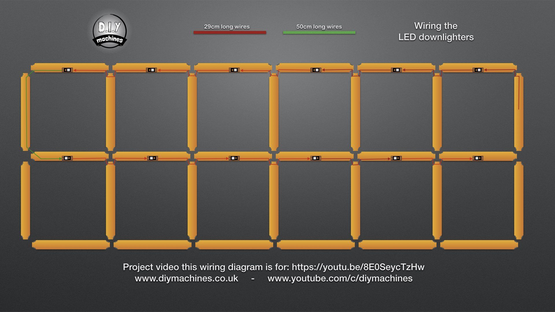
In the C++ code, comment out _12_HR_CLOCK and uncomment _24_HR_CLOCK in Config.h. Width and Height should automatically reconfigure to support this. If you wired everything exactly as I did (see image below), you don't need to make any more configuration changes in the C++ code. Otherwise, follow the steps below.
Last thing you may need do is to go into Config.h and modify the segmentWiringOrder, spotlightWiringOrder, h_ten[], h_one[], m_ten[], and m_one[]. The first array tells the program how you wired the clock, so each number in the array is the lighting index that segment covers. The numbers in those last 4 arrays should be the lighting (not wiring) index. The image below is the wiring order that is coded into the program right now. However, if your wiring order is not the same, you have to reference in what order your segments are wired. See the code in Config.h to learn in what order to put it in.

Create a file called "Secrets.h" with the following code. Replace the placeholder text with the relevant information:
const char PROGMEM *ssid     = "Your WiFi Name Here";
const char PROGMEM *password = "Your WiFi Password Here";| Variable | Description |
|---|---|
| ssid | Name of the WiFi point to connect to. Otherwise the clock will not sync and you can't connect to the webserver |
| password | Password to the WiFi point |
Located at the bottom of the webpage once you have everything setup. If you forget these commands, you can type help to bring this list up in the webserver
| settings | For debug, shows all settings stored on the device | settings |
| utcoffset | Sets your UTC offset in hours. This only needs to be done once, and is saved on reset in EEPROM | utcoffset -8 |
| rainbowrate | This changes how rainbow-y the rainbow is. By default, this value is 5 | rainbowrate 3 |
| fps | Set the frames per second of the display. Default is 30, Its fast enough to do 60, but all effect speeds are fps-dependent | fps 24 |
| reset | Factory Reset settings, including UTC offset | reset |
| resetprofile | Factory Reset lighting settings, but doesnt reset UTC offset | resetProfile |
| hyphen | Sets the hyphen width for the hours/minutes seperator | hyphen 9 |
| hyphencolor | Sets the hyphen color | hyphencolor ffa400 |
| save | Saves all settings without waiting for the save counter | save |
| reboot | Restarts the device after 3 seconds | reboot |
| restart | Alias for reboot | restart |
This is to modify some settings in case your setup is not wired exactly like mine. I've bolded any settings that you would most likely need to modify
| Variable | Description |
|---|---|
| LEDS_PER_LINE | Should be 9 unless you want to use 30 LEDs/m or 144 LEDs/m |
| MILLI_AMPS | Amperage rating of the power supply. I used a 12v 3A supply and used 2 buck converters to step down. Wired half of the LEDs to the first buck converter, and half to the 2nd. I do not really recommend doing it like this since it does heat up quite a bit when it runs at 100% brightness on white (~90c) which could deform PLA. I have a heatsink on it to reduce heat, but the lack of airflow is concerning |
| FRAMES_PER_SECOND | Shouldn't be above 30 or else some timing stuff may lag behind. If you don't mind, you can set to 60 |
| _12_HR_CLOCK | 12-hour clock layout. This is selected by default |
| _24_HR_CLOCK | 24-hour clock layout. Requires additional segments and LEDs. See Setting to 24hr layout above to change the layout to 24hr |
| LIGHT_SENSOR | Should be connected to A0, since thats the only analog pin on the board |
| DATAPIN | Connected to D8 on my NodeMCU v0.9 (pin 15) |
| SPOTLIGHTPIN | If following the original instructions, they use a seperate pin for the spotlights. If so, uncomment this line and set to the respective pin number |
| LED_TYPE | Should be WS2812B's in most cases |
| COLOR_ORDER | WS2812B's are GRB. If colors act weird or you are using other LED_TYPE's, you may need to switch to RGB |
| NAME | Name of the ESP8266 device (used to connect or as an identifier so you know what device is which in the routers "device" page |
| EEPROM_UPDATE_DELAY | How many seconds to wait after a change before saving it to EEPROM. This is to reduce writes to EEPROM so we don't wear it out |
| framesPerSecond | Set to 30 by default; maximum FPS. Usually Gradient is the most intensive one at around 45fps at least for all effects |
| AUTOBRIGHTNESS_DELAY | How many seconds to wait before getting another reading from the light sensor for auto brightness |
| AUTOBRIGHTNESS_SAMPLES | How many samples to average for auto brightness |
| segmentWiringOrder[] | Compensates for the difference between how the code references segments and how its actually wired. The wiring order goes from 1-2-3-4-5-6-7... in the order it is wired. If the direction of the wiring points towards the bottom right, the number is positive. If the direciton of the wiring points towards the upper left, the direction is negative. This is to both make effects easier without needing to hard-code any values. The numbers in the array represent the position of the segment it covers. The way I wired it was starting at segment 7 moving upwards, then moving right across segment 1, then down to segment 8, right to segment 14, and so on. |
| spotlightWiringOrder[] | Same as above, but for spotlights. Starts at 0 this time since we don't need +- signs. If you don't have any spotlights, just leave this alone |
| m_one[] | segment indicies for the ones digit for the minutes |
| m_ten[] | segment indicies for the tens digit for the minutes |
| h_one[] | segment indicies for the ones digit for the hours |
| h_ten[] | segment indicies for the tens digit for the hours |
| BACKLIGHT | Optional support for backlighting behind the clock. Note if you enable this, set const enableBacklight = true; in data/config.js |
| BACKLIGHT_PIN | Seperate pin to handle backlighting if enabled |
| BACKLIGHT_TOP_LEFT|RIGHT | Direction where the wiring of the LED's for the backlight starts at |
| BACKLIGHT_[COUNTER]CLOCKWISE | Direction the wiring of the backlight goes around the board |
| BACKLIGHT_WIDTH | Number of horizontal LED's in the backlight. This assumes there are the same number of LED's on the top and bottom |
| BACKLIGHT_HEIGHT | Number of vertical LED's in the backlight. This assumes there are the same number of LED's on the left and right side |
You may need to change the settings if you use a 192.168.0.# local IP address or want to change to a different static IP address. I would not recommend using DHCP since I usually find more success connecting via IP address instead of the hostname (you would need to modify more code if you wanted to use DHCP anyways). To find your IP, you can type "ipconfig" on Windows in cmd or "ifconfig" on Mac/Linux in terminal to find this IP. Usually it is 192.168.0.1 or 192.168.1.1 for home networks.
| Variable | Description |
|---|---|
| ip | Static IP Configuration so you can connect using a 192.168.#.# address |
| gateway | IP address of your router |
| subnet | Subnet address of your home address. If you don't know what this is, you probably wont need to touch it |
| deviceName | The domain in use for mDNS. Default is ledshelf.local for deviceName = "ledshelf" |
When the Wi-Fi module sends/recieves data, it flashes the first LED in the strip. I am unable to trace exactly where this is coming from, so I recommond having a sacrifical "Wi-Fi status" LED right before the strip. All you need to do is uncomment the #define SACRIFICELED line to enable. Otherwise, the flashing should be fairly infrequent except for NTP time updates and webserver actions.
Run this command if you have git installed. Otherwise just download the repo zip file in the top right and extract:
git clone https://github.com/Winston-Lu/LED-Clock- Download and open the Arduino IDE
- Go to "File" > "Preferences"
- Under "Additional Boards Manager URLs:", add
http://arduino.esp8266.com/stable/package_esp8266com_index.json. If you have entries there already, add a comma to seperate them - Click OK and go to "Tools" > "Board" > "Board Manager"
- Look up "esp8266", then install the board
- Once it's installed, go to "Tools" > "Board" > "ESP8266 Boards" > "Generic ESP8266 Module". This will work for the NodeMCU v0.9 and NodeMCU v1.0.
- Change flash size to "4MB (FS: 1MB OTA ~1019MB)"
- Once you plugged in your ESP8266, select the COM port it is connected to. You can leave every other setting default
- Download the LittleFS tool from this repository here
- Follow their installation instructions and under "Tools", you should see "ESP8266 LittleFS Data Upload"
- Click on it and let it upload the webserver code
- Create a
Secrets.hfile and modify the settings accordingly. Read above for how to configure your Wi-Fi settings and other important settings. - Upload the Arduino code by clicking the right-facing arrow near the top left.
- After that, you should be done. Plug the ESP8266 in and start configuring some web settings such as the UTC offset by going to the webserver (Default http://LEDShelf.local or 192.168.1.52), scrolling to the bottom, and typing in the
utcoffsetcommand. This is meant to be configured online since daylight savings would make updating this a hassle


Connect 2 red wires to the 5V line on the LED strip, one connected to the 5v power supply and 1 to the LED strip female header red wire. Do the same for the black wires: 2 coming from the GND pad on the LED strip, one to GND on the power supply and 1 to the GND pin on the female LED strip connector. For data, we only need 1 wire coming from the LED strip data line into the female connector (usually in the middle). Once you get that setup, you should be able to hotswap the module in case you want to do any testing and don't want to setup Arduino OTA uploads. If you don't want to hotswap, you can just solder directly onto the board's VIN, GND, and D8
- A 3D printer. Any cheap printer would work, but it would need a bed size of at least 150mm x 150mm to print the wall segments. The wall piece is about 180mm long
- Screwdrivers and/or a drill helps
- Tweezers to run wires through the bracket holes
- 1kg of filament for the 31 + 1 brackets, as well as the diffusers. I recommend White filament (I used PLA, but PETG or ABS is fine too)
- You can skimp out on infill (~10-15%) for the brackets, but the load bearing ones should be higher
- I would print them lying on the side, as we dont really care about overhangs and layer lines would be perpendicular to the load
- DIY Machines printed them vertically, but with weaker filaments like PolyLite, printing horizontally would be much better
- That way the load will be going perpendicular to the layer lines (The point that usually fails first), while the almost non-existant transverse strain will go against the layer lines
- Overhangs won't look too great, but we won't be looking at them
- 3kg of wood or brown filament (PETG or PLA works). This is for the shelf covers. You will use about 2.6kg, not including any failed prints/filament change purges
- A Wood panel. I used a 3/4in x 2ft x 4ft piece of Plywood from Home Depot. I wouldn't recommend anything smaller for a 12hr shelf
- >64 #8 Wood screws. 64 would be the minimum (2 per segment)
- Cabinet/Painting mounting bracket to mount to the wall
- A handful of wire, preferably of red, black, +1 other color. Buying a set from Amazon will be more than enough
- A soldering iron and some solder
- A LED power supply (Recommended >40w power supply). The LED's are 5v, so I would go with a 5v power supply. If you go with a 12v, you must use 12v LEDs or you must step down to 5v using a step-down buck converter
- An ESP8266. You can get these on Amazon or Aliexpress.
- 5m 60 LEDs/m Addressable RGB LED strip. You can go with a 30 LED/m strip, but you will have some dark spots, or you can go with 144 LED/m with a 2.4x increase in power usage for the tradeoff of having really bright lights such that it will probably shine through the shelf walls.
- A computer to upload code with a micro USB cable
- Hot glue gun and/or adhesives
- Terminal blocks if you don't want to solder as much
- Photoresistor + 10k ohm resistor if you want autobrightness
- Buck converters if you want to use an existing laptop power supply to step down to 5v (I would recommend at least 2 or 3. 2 buck converters start to overheat at 100% load after 45 minutes or so)
- Each wall segment takes about 3 hours to print each. I would print them horizontally and not vertically as shown in the original video to get stronger prints
- Each wall takes about 8 hours to print each. The first 3 layers are printed in white PLA, while the rest is with wooden PLA (or whatever plastic you use)
- You only need 1 of the layout template. Remember to measure twice and drill once
- The STL files for these parts are in the original video description, so give him some support by going to the video.
Effects are rather hard to create since we're working with segment indicies going in different directions. Since this doesnt translate nicely to a 2D array, most effects I've made relies a lot on regression, so it makes the code very difficult to read and initially understand. If you have any ideas or suggestions, put it in the discussions tab
All effect rendering is done in the Lighting.cpp file, usually in the showLightingEffects() function near the top.
All effects use a single buffer layer that FastLED requires before pushing the data to the display. That means all effects are rendered ontop of one another in the same layer, so any segment color data that gets rendered under another effect (EG clock) will be lost. This isn't a big deal, as I calculate the color of each effect manually each frame, which isn't the most efficient but the ESP8266 is fast enough to handle it at ~30fps. The spotlights effects get rendered first, then the background, then the clock segments. When the clock renders, it overwrites the segment colors in the background and applies the clock brightness setting on the affected segments. Clock transparency allows for the overwritten segments to mix the color between the background and foreground clock if desired.
When creating a new clock effect, it is recommended to create a seperate function to calculate the LED colors per segment seperately and independently. That way you follow the previous existing code that handles switching the necessary segments.
- For the clock, it uses the settings in
Config.hto determine which segments are responsible for the 7-segment digit display - For the background, it goes through all segments and applies the effect one-by-one or uses the
gridstruct to work on the entire display like a 2D array - For the spotlights, it goes through all spotlights and applies the effect one-by-one or just works off the 1D spotlight color array (used like a 2D array)
- Note that spotlights[] and leds[spotlightToLedIndex()] work differently. Since effects will overwrite some color settings for spotlights, I had to keep the two seperate. spotlights[] keeps track of the color data, while leds[spotlightToLedIndex()] puts colors onto the array that will be rendered
- Using a 1D array for simplicity.
- If you need Y, bounds are [0,HEIGHT)
- If you need X, bounds are [0,WIDTH)
- To loop through the array using x and y: (You can use
size_t,int,uint8_t,uint16_t,uint32_t, or whatever)
for(size_t y = 0 ; y < HEIGHT ; y++){
  for(size_t x = 0 ; x < WIDTH ; x++){
    //spotlights[y][x] equivalant
    leds[spotlightToLedIndex(y*WIDTH+x)] = ...;
  }
}
I have a few functions that make creating effects easier
| Function | Description |
|---|---|
| strip segmentToLedIndex() | Returns a strip struct, which contains the first LED index (top-left most LED index) and if the effect should be reversed (pointing to the top left rather than bottom right, so count down rather than up). If the first LED index is 27, strip is in reverse, and LEDS_PER_LINE is 9, then the LEDs are [27,26,25,24,23,22,21,20,19] moving up or to the right |
| int spotlightToLedIndex() | Returns the LED index in the leds[] array of a spotlight |
| struct grid2d | Meant to represent the lights in a more 2d way split into a vertical and horizontal segment portion. Used in the rain effect |
| URI | Parameters | Description | Example |
|---|---|---|---|
/getsettings |
Gets the current clock settings | /getsettings |
|
/power |
value=true,false |
Turns the clock on or off | /power?value=true |
/transparency |
value=0-255 |
Sets clock transparency from opaque 255 to transparent 0 |
/transparency?value=127 |
/foregroundtransparency |
value=0-255 |
Same as /transparency |
/foregroundtransparency?value=127 |
/autobrightness |
value=true,false |
Toggles autobrightness | /autobrightness?value=true |
/brightness |
value=0-255 |
Clock segment brightness | /brightness?value=200 |
/backgroundbrightness |
value=0-255 |
Background brightness | /backgroundbrightness?value=150 |
/spotlightbrightness |
value=0-255 |
Spotlight brightness | /spotlightbrightness?value=255 |
/bgcolor |
red=0-255 green=0-255 blue=0-255 |
Sets the primary colour of the background | /bgcolor?red=10&green=100&blue=255 |
/bg2color |
red=0-255 green=0-255 blue=0-255 |
Sets the secondary colour of the background | /bg2color?red=10&green=100&blue=255 |
/h1color |
red=0-255 green=0-255 blue=0-255 |
Sets the colour of the hours tens digit | /h1color?red=10&green=100&blue=255 |
/h2color |
red=0-255 green=0-255 blue=0-255 |
Sets the colour of the hours ones digit | /h2color?red=10&green=100&blue=255 |
/m1color |
red=0-255 green=0-255 blue=0-255 |
Sets the colour of the minutes tens digit | /m1color?red=255&green=255&blue=255 |
/m2color |
red=0-255 green=0-255 blue=0-255 |
Sets the colour of the minutes ones digit | /m2color?red=255&green=255&blue=255 |
/spotcolor |
value=0-num_spotlight red=0-255 green=0-255 blue=0-255 |
Sets the colour of the spotlight at index num_spotlight |
/spotcolor?value=2&red=255&green=255&blue=255 |
/effectfg |
value= off solid rainbow gradient |
Sets the active clock effect | /effectfg?value=rainbow |
/effectbg |
value= off solid rainbow gradient rain sparkle fire loop |
Sets the active background effect | /effectbg?value=loop |
/effectsl |
value= off solid rainbow gradient rain sparkle fire |
Sets the active spotlights effect | /effectsl?value=sparkle |
/utcoffset |
value=### |
Sets the UTC offset in hours, supports decimal and negative values | /utcoffset?value=-3.5 |


