vorondesign / voron-documentation Goto Github PK
View Code? Open in Web Editor NEWSources of the documentation website for all Voron 3D printers
Home Page: https://docs.vorondesign.com/
License: GNU General Public License v3.0
Sources of the documentation website for all Voron 3D printers
Home Page: https://docs.vorondesign.com/
License: GNU General Public License v3.0


https://github.com/VoronDesign/Voron-Documentation/blame/main/build/software/skrPico_klipper.md#L93
With the Pico plugged into the Pi via USB-C and the boot jumper installed, press the reset button.
Important: If your Klipper installation is located on a USB-SSD, it is likely that it is mounted as "sda"!
Run the following command before proceeding to the next step:
lsblk
Now check which sd_1 is specified with 128M.
Use this sd_1 in the following step!
Next we need to mount the SKR Pico to the Raspi to copy the file (klipper.uf2) over
The link to 120decibell's macros on https://docs.vorondesign.com/community/macros/ is broken and gives a 404.
[https://docs.vorondesign.com/build/startup/#bed-locating-v1-trident-legacy](Bed locating (V1, Trident, Legacy)
Y and X seem to be switched.
The Z endstop should be located at close to max X position
Doesn't make sense since z endstop on trident is located on the bed frame which is in the middle not at max X.
A the bottom of the page https://github.com/VoronDesign/Voron-Documentation/blob/main/community/troubleshooting/shiftingtech/printer.cfg_changes.md
Is a link "build docs" this points to https://docs.vorondesign.com/official/build/software
This is a 404 error. Page not found
V0 Docs on docs.vorondesign still document V0.0/1 Z-endstop setup. see https://docs.vorondesign.com/build/startup/#z-endstop-location-v0. New position of Z-endstop either needs an added paragraph/section or the current section needs reworked.
Hi,
Thanks for putting these docs together, they're amazing. One small thing I spotted is that the conversion from AWG to mm2 for mains AC wiring in the tips section of Electrical Wiring seems off compared to most conversion tables I've seen.
https://www.cse-distributors.co.uk/cable/technical-tables-useful-info/awgmetric-conversion/
https://www.multicable.com/resources/reference-data/cross-reference-awg-to-mm2/
I'm not 100% sure which value is meant to be the correct one otherwise I'd update it myself.
Thanks!
Hi, the materials section of the website(https://docs.vorondesign.com/materials.html) has misleading information.
It says that the Nylon has a Tg (glass transision temperature) of 180C. That is false, it has a Tg around 60-75C but has a 0.45MPa heat deflection temperature of around 140-180C, depending on the type of Nylon and blend.
The Tg is defined by the softening temperature of the amorphous phase. A github ticket is not the place to give a course on semi-crystalline thermoplastics but it roughly means that the Nylon will only hold its shape up to 120-140C only when it is weakly loaded. Nylon's glass transition is not as sharply defined as other common plastics and creep increases significantly when its amorphous phase is softened. Hence I do not think it is wise to say it is a "viable option" for anything that is loaded, inside the chamber, especially on anything near the heatbed. I am not sure either where the comment about PA12 being more resistant to creep than PA6 comes from...
This section also says that the PETG has a Tg of 55-60, which is also false. It is around 80-85C.
I would change the Nylon paragraph for the following:
Nylon (PA6 and PA12) has a low glass transition temperature but some blends can withstand temperatures of 180C when under a minimal amount of load. It has moderate stiffness and moderate ductility. It is not recommended for Voron parts due to the tendency to creep (slowly deform) under the constant pressure exerted by the bolts clamping on the parts.
Have a look at https://docs.vorondesign.com/build/electrical/v2_flyf407zg_wiring.html
Connect USB Cable to your SKR 1.4, but do not connect it yet to your Raspberry Pi
In the section for the M141 gcode macro, the example is using a deprecated Klipper function default_parameter. Newest Klipper requires this syntax.
[gcode_macro M141]
#default_parameter_S: 0 (removed)
#default_parameter_P: 0 (removed)
gcode:
{% set S = params.S|default(0) %}
{% set P = params.P|default(0) %}
SET_TEMPERATURE_FAN_TARGET temperature_fan="chamber" target={S}
Tested this on my V2.4 with latest Klipper, everything else is fine. Thanks for the great docs!
Larry
The "software Configuration" page (https://docs.vorondesign.com/build/software/configuration.html)
Is missing a base configuration for the BTT Octopus board.
This is the board that many voron2.4 kits are shipping with these days, so having a base drag and drop configuration for it would be nice.
Also, for downloading the config file to the klipper host, why not download it directly using wget or something?
instead of
cp ~/klipper/config/FILENAME_OF_VORON_CONFIG.cfg ~/klipper_config/printer.cfgjust do:
cd ~/klipper/config/wget https://raw.githubusercontent.com/VoronDesign/Voron-2/Voron2.4/firmware/klipper_configurations/Spider/Voron2_Spider_Config.cfgcp ~/klipper/config/Voron2_Spider_Config.cfg ~/klipper_config/printer.cfgor something like that?
does this account for different config paths between mainsail/octoprint? if that's a thing? i'm new to klipper so i don't know.
instead of using nano to edit the config, all 3 print managers have config editors (if octorprint has the recommended klipper plugin). would it be better to use that?
The Updating Printer Specific Settings section doesn't tell you to uncomment in the [gcode_macro G32] section (which is mentioned in the default printer.cfg as "things to check"). This is very bad, as failing to do so will result in the nozzle crashing into the z-endstop when starting the first print. (Don't ask how I know 🙈)
Hi,
the reference for Trident on https://docs.google.com/spreadsheets/d/1njgHapSZLiQHobrEVkeuAuhhDsXzFOJOiIpvfVFeGxQ/edit#gid=1307873836
is outdatet. Please update
Best regards
Markus
The bed leveling section reads:
V1, SW, Legacy: Z_TILT_ADJUST, SCREWS_TILT_CALCULATE
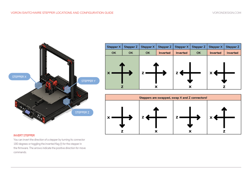
A user tried to enable Z_TILT on a Switchwire because they misunderstood this. Also the reference to the Trident is missing.
I'll take care of this change, this issue is so that I don't forget.
The link is broken to sensorless homing guide in the Voron documentation website.
Link found on https://docs.vorondesign.com/build/startup/
-Incorrect path https://docs.vorondesign.com/build/startup/Voron-Documentation/blob/main/community/howto/clee/sensorless_xy_homing.md
-Correct path https://docs.vorondesign.com/community/howto/clee/sensorless_xy_homing.html

The Voron v0.0 documentation does not mention adding a ground wire to the AC bed at all. Or is this for some reason not needed?
Right now, the documentation and all sample configs refer to using ls -l /dev/serial/by-id. This gives the problem that users often miss out on the /dev/serial/by-id part, and in addition often users don't remove the <>. This curently happens on a daily basis, if not multiple times per day.
Proposed fixes:
ls /dev/serial/by-id/* which gives the full path which can simply be copy'n'pastedThought this might be useful for all the people with PL-08N2 that want to keep them. Mine works great, good accuracy. Also, it is the cheapest probe option by far.
In going to the MGN12 rail I realized that my PL-08N2 was to tall, and now understand, from Steve Builds channel, it is no longer supported from trident forward.
But!!! The top of the PL-08N2 housing can easily be removed with pliers to be cut down so it fits with the new MGN12 trident carriage. I think this should be part of the documentation or at least common knowledge. Why waste all those probes if they are working well, and then shell out more cash for Omron's.
I hope this will be included in the documentation or at least pinned in the discord.


Docs suggested use of FluiddPi but FluiddPi states:
WARNING: FluiddPI is not under active maintenance and we've had reports of users finding issues while using it. As such, our recommendation is that you do not use FluiddPI, and instead use KIAUH to install Fluidd.
Suggest the docs be changed in favor of Kiauh.
This guidance should be removed from the endstop check section as the issue is most often a wiring issue. Users see this section and invert their endstop pins thinking that's the cause, which just adds another issue that needs fixing later on.
owners: apologies if this isn't the correct place. i can't seem to find the source of all of the assembly guides for all revisions. Just the PDFs here in this repo, and other repos.
Hello! The assembly manuals are awesome. Love the font, scheme, clearness, etc.
As I have purchased/sourced my parts for my 2.4 build, and starting to dig deep into Voron User mods, many many live streams of assembly (Tom, Nero 3dp, etc), and reading 1000s of chats, there seems to be a common theme that I haven't seen addressed yet. I can sum it up by repeating what I saw Nero 3DP enter into the chat multiple times over Tom's live streams of his 8 part series (oh yeah, I watched all 24 hours of it!!), along with other dev members/community members...
The manual needs to be updated.
(and) There's a running list.
Therefore, I would like to propose a different approach to these Assembly Manuals:
Place the source of the manuals online, and generate them from source (e.g. LaTeX) to iterate on them much faster. Also, tracking changes and allowing members to submit PRs in a central place.
I know the chaos this sounds like: opening up the precious documents to possibly 1000s of people thinking this or that needs to be changed. But, hear me out...
That last one is key: a central place to expose the current source of the assembly manuals, along with upcoming changes to those manuals.
It would help iterate the manual revisions much faster. Merge PR into master/main, manual gets rebuilt, pushed out to the appropriate repo automatically - daily.
If that "running list" are the Issues in this repo, then it looks like we are missing the online source piece. And it would default to someone still having to read the issue, verify the change, confirm it works, update the docs (wait for other changes), and then release a new one.
in the build/startup -> Saving your results
there's a link clarifying importing details of WHERE to save your results. someone in discord literately had the same confusion as me trying to figure out why these values dont really work as expected.
please make the link more visible. currently it looks like its just some community comments instead of necessary steps.
In the secondary printer duning doc where it referes to Mesh Points and Relative Reference Index there is formula for calculating the reference index so it is the point at the center of the bed. It currently suggests using ((x points * y points) - 1) / 2
On a 3x3 mesh that gives an index of 4 which is on the edge of the bed. With larger mesh numbers the error is lower but it is still the probe point next to the center of the bed rather than the center.
The formula sould be ((x points * y points) + 1) / 2
On a 3x3 mesh that gives us probe point 5 or the center of the bed mesh.
On a 5x5 mesh that gives us probe point 13 (the 3rd point on the 3rd row) or the center of the mesh. point 1 to 5 is row one, point 6 to 10 is row two, point 11 to 15 is row three and the middle point is 13.
https://docs.vorondesign.com/build/electrical/mini12864_klipper_guide.html
A user recently had a problem getting the display working, misunderstanding the header flip image and thinking "yes" meant to flip one connector, and "no" meant to not flip the other. Suggestion:
The color scheme of the docs site gives titles a very low contrast ratio. Being colourblind, this makes them hard to read.
Updating the color scheme to follow WCAG 2 guidelines would provide a much better experience for general users and improve readability for users that have issues with their vision
WAVE report
WhoCanUse Contrast Assessment
Updating the theme provides an opportunity to update the design tokens found in voron-dark.scss to be self-documenting. For example, having tokens such as background-dark and on-background-dark instead of grey-dk-400 and voron-red-60. This could help to reduce design issues in future changes
A note should be added to either the assembly guide or the build page that mentions that loctite on the motor grub screws should be left off until the pulley is fully aligned with the belt path. People have reported issues with putting loctite on early then not being able to move the pulley since the grub screws are fixed. (Admittedly this shouldn't happen with 242, but people are people)
Building a Voron v0.0 and was extruding way to much extra filament to be a simple rotation_distance inaccuracy. Turns out I had the wrong gear ratio in the config. (50:10 instead of 50:17) I searched the github and website and could not find where the gear ratios were. Seems they are not documented, at least not very well. Only solution was to ask on the discord.
The V2 description needs to be updated to be inclusive of both dual smaller MCUs and single large MCUs.
Using the instructions on the Initial startup guide page to set (0,0) has some problems. My nozzle is still over the bed at (2.3, 2.6) and using the documentation on the page suggests changing position max in this paragraph:
If X and Y offsets are within 5mm or 0,0 is past the bed, the postition_max values should be adjusted to change where the 0,0 point is computed. If the 0,0 is over the bed, the distance from the home point to the front left (position_max) must be increased. If the 0,0 is past the bed, the distance must be decreased. The amount is determined by the output of the M114 command. Update position_max for both [stepper_x] and [stepper_y] as follows:

For X: New = Current - Get Position X (M114) Result
For Y: New = Current - Get Position Y (M114) Result
In my case this results in a position_max that is smaller than the endstop_position, leading to klipper throwing an error. This has been suggested to fix by changing both endstop_position and position_max, which I am testing now.
EDIT: Changing both parameters to the same value allows me to move to 0,0 above the bed without issue. Thank you Timmit for the suggestion!
Mil-Spec: M22759/9-22-9
This is 22awg silver plated, stranded wire used in fighter jets with the Mil spec code branded on the cable with the wire gauge. Mil spec, this stuff is the real deal. There are countless other specs, it just happens that 22awg is what I use. 12-24 is relatively easy to get ahold of someone who has stock. In twisted pair you can get 26 and 28 pretty reliably but its harder to check the milspec number on those to make sure you did not get conned and I have crazy good vision.
Also it is $0.63 per meter or $0.19 per foot when buying cut-offs. If you get a whole spool you get a deal, I bought 300 meters for $90 and walked away VERY happy especially when I was previously quoted $6.6 per meter. There are plenty of vendors that have their own website, google search "military surplus ptfe hook up wire" and you will see many options. This stuff is basically an endless supply of the best wire for 3D printing at a huge discount.
Here is one of the dedicated websites: https://www.surplussales.com/Wire-Cable/Wire4.html
There are many more, I just did not think it was worth it to dig them up atm.
Please let me know your thoughts :) I have been thinking of scrubbing and seeing if I can come up with more contributions. This is basically me dipping my toes in the water. Perhaps next time ill try doing it as a pull request, but I have not used github much or know the etiquette.
How to block it in Google Analytics:
https://botcrawl.com/block-s-click-alieexpress-com-referrer-spam/
What it is:
https://en.wikipedia.org/wiki/Referrer_spam
There is no command for trident in the section of bed leveling.

Thank you so much for keeping Voron outstanding, we appreciate it, a lot!
I noticed that in the second bullet point on the Mechanical Assembly page, length is spelled lenth.
.... on
https://docs.vorondesign.com/build/slicer/first_print.html
first link is wrong
Can we add to https://docs.vorondesign.com/build/startup/#xy-homing-check
Once there is a tested process for stopping the printer in case of something going wrong, send a G28 X Y command. This will only home X and Y but not Z. The tool head should *move up slightly and then move to the right until it hits the X endstop, then move to the back of the printer until it hits the Y endstop. In a CoreXY configuration, both motors have to move in order to get the toolhead to go in only and X or Y direction (think Etch A Sketch). If the gantry moves downward first before moving to the right, you must reverse your z stepper directions in the config.
Klipper has been updated
Z_ENDSTOP_CALIBRATE command now opens a popup screen that gives you buttons to adjust you z offsset instead of using TESTZ Z=*
I've recently assembled v0.1, and was following the startup guide at Motor Configuration Guides.
I might have jumped the gun there, but since I was in the process of debugging stepper motors and directions (so was live), and the guide told me that motors are swapped I went ahead and changed them. The doc states: If the motors are going in directions that match the lower row of the chart, physically swap your X and Y (A and B) motor connectors on the MCU.
Only later when I scrolled down, I saw the warning:
Important: Do not unplug or re-plug motors from MCUs without powering down the printer. Damage to MCU may result.
Since there's risk of damage, the warning probably should be the first thing the user sees, before any other action is directed.
I couldn't find the klipper firmware configuration to flash the firmware for the Octopus Pro H723 board. I asked Bigthreetech and they gave me this info. Maybe you could put it in the octopus pro doc. for other people.

At the end of the docs page Slicer Setup there is a link to macro page. That link is broken "page not found". It may be altered to https://docs.vorondesign.com/community/macros/ ?
I think there should be a "common issues" section with troubleshooting checklists for each printer/component in the docs. I just encountered something that has to be a common issue with extrusion:
I opened the door to my AB after hearing some clicking noises, expected a clog but there was no clog at all. used a small screwdriver to poke at the nylon gear and I could move it back and forth a little bit, affecting the bondtech gear too. So I took everything out and placed a 1mm thick M5 washer at the foot of the nylon gear, put everything back - viola! No more clicking and extrusion is 👌 This could be under Afterburner > Clicking/knocking during extrusion, grouped together with clog/jam/skipping steps as a possible cause of the clicking.
However, me being new to the Voron universe I don't really feel I could make a PR for this already since there are many people with much more experience with issues that can arise that could get this started. This might save a lot of time in the Discord as many of these troubleshooting discussions happen over and over and can be tricky to find via search still. So one could refer to the troubleshooting docs first before asking the questions.
What do you guys think?
It appears that for at least one of the diagrams the labelling for X and Y corresponding to A and B are switched. X is labelled with A and Y is labeled with B, which should be reversed to X/B, Y/A.
There is a section in the documentation that may be better worded.
Under "Filament Tuning" "A temperature tower help identify the ideal temperature for a filament." may be better worded as
For each filament, a temperature tower helps to identify the optimal temperature. or Each filament has different temperature ranges that can be optimized with a temperature tower.
Thank you for any consideration to better communicate to this great community!
https://docs.vorondesign.com/build/electrical/v2_spider_wiring.html
"BTT mini12864 only remove components R1, and C6, and rotate the connectors 180 degrees
See the mini12864 guide'
Yeah....no.

Maybe just tell people to cut the housing with flush cutters...wish Id cut the housing.
Page 48 in the manual has an option for removing a part if using a hall effect endstop, along with a link to documentation. Visiting the link https://voron.link/hxd3cv0 goes to a page where the first sentence says
"The hall effect endstop is only designed for a V2.4. It will not work on any other models!"
If this is not applicable to the Trident, then suggest the mention in the manual be removed entirely.
If it could be applicable to the Trident, then this linked page should be updated to mention the Trident as well.
On this page:
https://docs.vorondesign.com/build/electrical/v2_octopus_wiring.html
There is a section (and the image at bottom) that refers to motor A as "gantry left" and motor B as "gantry right".

I find this confusing - if not contradicting the manual which refers to motor A as being on the right hand side of the gantry (when looking at the printer from the front).
Am I missing something that makes it "gantry left"?
ssh [email protected] is supported by Windows via Command Prompt and by MacOS/Linux via Terminal. No reason to list a bunch of different software on different platforms when the same thing works on all platforms.
You can transfer files via a GUI program on Windows, Linux, and MacOS with FileZilla. Use that instead of mentioning different software for each platform.
These two thing will help to clean up documentation a little bit by keeping things the same between platforms.
Voron Design online document still states and links to the V0.1 docs as the current build manual.
Note: RGB and RGBW are different and must be defined explicitly. RGB and RGBW are also not able to be mix-and-matched in the same chain. A separate data line would be needed for proper functioning.
Support for this was aded for the Rainbow Barf mod
https://github.com/tanaes/whopping_Voron_mods/tree/main/LEDs/Rainbow_Barf_Logo_LED
Here is the pull request
Klipper3d/klipper#5409
Hello,
after BIGTREETECH release the SKR Pico, i think the guide should be updated for this mainboard.
It is specific for the voron 0 setup with a mounting position for the raspberry pi.
✌🏻
On the Mini12864 documenation, it tells you to remove certain components from the display board. In the case of BTT, it's R1 and C6. However, the display seems to work fine (at least for BTT), so an explanation of why this is needed would be nice. Also, if this is important, the assembly manual would benefit from a link to that documentation page in the relevant assembly steps.
A declarative, efficient, and flexible JavaScript library for building user interfaces.
🖖 Vue.js is a progressive, incrementally-adoptable JavaScript framework for building UI on the web.
TypeScript is a superset of JavaScript that compiles to clean JavaScript output.
An Open Source Machine Learning Framework for Everyone
The Web framework for perfectionists with deadlines.
A PHP framework for web artisans
Bring data to life with SVG, Canvas and HTML. 📊📈🎉
JavaScript (JS) is a lightweight interpreted programming language with first-class functions.
Some thing interesting about web. New door for the world.
A server is a program made to process requests and deliver data to clients.
Machine learning is a way of modeling and interpreting data that allows a piece of software to respond intelligently.
Some thing interesting about visualization, use data art
Some thing interesting about game, make everyone happy.
We are working to build community through open source technology. NB: members must have two-factor auth.
Open source projects and samples from Microsoft.
Google ❤️ Open Source for everyone.
Alibaba Open Source for everyone
Data-Driven Documents codes.
China tencent open source team.