
![]()
![]()
Check out the Documentation for more information on usage, configuration, and development.
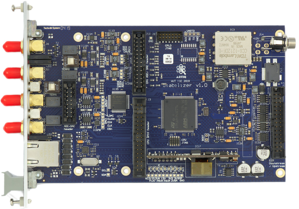

Firmware and software for the Sinara Stabilizer module with high speed, low latency ADC/DAC data processing and powerful DSP algorithms in between
Home Page: http://quartiq.de/stabilizer/
License: Apache License 2.0
![]()
![]()
Check out the Documentation for more information on usage, configuration, and development.
![bors[bot] avatar](https://avatars.githubusercontent.com/in/1847?v=4 "bors[bot]")

![dependabot-preview[bot] avatar](https://avatars.githubusercontent.com/in/2141?v=4 "dependabot-preview[bot]")
![dependabot[bot] avatar](https://avatars.githubusercontent.com/in/29110?v=4 "dependabot[bot]")


To make MQTT easy to deploy on Stabilizer (and Thermostat, Thermostat_EEM, Driver, Booster, Humpback etc.) we need to reduce it's footprint in the code by developing some kind of framework.
For Stabilizer we have currently to route the json-over-TCP requests:
Lines 109 to 158 in 66c917b
For Booster there is a sizeable amount of request routing, deserialization, serialization code. Adding a setting or telemetry quantity to the stack requires multiple adjustment in several different places.
(ripped from #147): Stabilizer is somewhat similar to redpid (https://github.com/quartiq/redpid). Redpid has a pretty convenient solution to the settings/status problem. For migen/misoc we have a very generic way of configuration-status-registers. They are instantiated in code with a single line (e.g. https://github.com/quartiq/redpid/blob/master/gateware/limit.py#L55) and then end up on a bus with mapping generated automatically (https://github.com/quartiq/redpid/blob/master/test/csrmap.py#L109).
This is very different from Stabilizer in terms of code (HDL versus machine) and transport/protocol (HDL bus CSRs over other buses and serialization versus MQTT) but the user-facing concept is the same: lots of knobs and displays on a big switchboard. The knobs being connected to settings and the displays being connected to telemetry.
Maybe for Stabilizer we want something similar (a named map of settings and status values).
The settings aspect should be double-buffered/paged/ping-pong to allow atomic updates of multiple settings synchronously without having to transfer the entire settings space.
And we need to think a bit about the status telemetry: There might be a case for configurable rates and suppression of some telemetry updates.
Dependabot couldn't find a Cargo.toml for this project.
Dependabot requires a Cargo.toml to evaluate your project's current Rust dependencies. It had expected to find one at the path: /stm32h7xx-hal/Cargo.toml.
If this isn't a Rust project, or if it is a library, you may wish to disable updates for it from within Dependabot.
This issue serves to extend on #54 and #24. Quartiq devices will be managed/interconnected over a network, how should that be implemented?
@jordens suggested MQTT as a suitable protocol. I’ve investigated that option a bit and will compare it with what we currently have. I’ll try to summarize the approaches, and distill features/requirements/use-cases served by aspects of those approaches. Please fill in whatever I miss.
Yeet JSON to a TCP port. This is what stabilizer supports currently.
MQTT is a message bus protocol that facilitates N to N connectivity (hub and spoke). It acts as a transport substrate on top of TCP and implements support for application level features such as QoS (unreliable, at least once / only-once delivery), N-to-N broadcasting, and some more. Classic request-response patterns are re-implemented on top of more generic MQTT constructs.
I’ve implemented a minimal MQTT client that can publish/subscribe (QoS=0) to a topic in ~200LoC. Running ejabberd as a broker was fairly straightforward.
dump:10.10.0.7:4567 to stabilizer_XYZ could trigger it to attempt to open a TCP socket to 10.10.0.7:4567 and stream samples over that socket)After flashing the firmware via the DFU interface no data is streamed out from port 1234. This seems to be due to the cycle counter not counting, and hence the block that periodically sends the IIR state never running.
Uncommenting this line solves the problem.
In retrospect I have also seen this problem occasionally even when loading the program via openocd.
During development of the HAL for Pounder support, a number of new modules were added to the existing stm32h7xx-hal repository, including:
These modules should be contributed back to the HAL if possible.
When I send a packet to the port (1235 by default), the firmware will panic at the socket.write_str() line of the json_reply() function in src/server.rs. The most observable symptom is that Pinging will stop to work after I send the packet. Using GDB, whenever I just send a packet to the TCP socket, the firmware seems to panic. Here is the backtrace:
^C
Program received signal SIGINT, Interrupt.
0x08024b28 in rust_begin_unwind (_info=<optimized out>)
(gdb) backtrace
#0  0x08024b28 in rust_begin_unwind (_info=<optimized out>)
#1  0x0801b3ca in core::panicking::panic_fmt () at library/core/src/panicking.rs:85
#2  0x08022f7c in core::option::expect_none_failed () at library/core/src/option.rs:1221
#3  0x0800ec38 in stabilizer::server::json_reply (socket=0x2001ac00, msg=<optimized out>)
    at /rustc/5099914a16a215794ad243df0cc7a05d91d168e0/library/core/src/result.rs:973
#4  0x08011aa4 in stabilizer::idle (c=...) at src/server.rs:127
#5  0x0801b32c in stabilizer::APP::main () at src/main.rs:160
I'd like to stress that this issue was not happening for the first few times I started using my Stabilizer v1.1 board. So far, I can't tell how to replicate this same issue on another Stabilizer.
Update: the error is produced because of a wrong sequence of supplying power to the board - see this reply. However, the need to use the OpenOCD command gdb_memory_map disable might still be needed in the latest unstable of OpenOCD.
When testing the JTAG programming option with the latest commit of OpenOCD (openocd-org/openocd@1457a1a), running openocd -f stabilizer.cfg would always produce the following error:
$ openocd -f stabilizer.cfg
Open On-Chip Debugger 0.10.0+dev-snapshot (2020-09-08-07:03)
Licensed under GNU GPL v2
For bug reports, read
	http://openocd.org/doc/doxygen/bugs.html
WARNING: interface/stlink-v2-1.cfg is deprecated, please switch to interface/stlink.cfg
Info : The selected transport took over low-level target control. The results might differ compared to plain JTAG/SWD
Info : Listening on port 6666 for tcl connections
Info : Listening on port 4444 for telnet connections
Info : clock speed 1800 kHz
Info : STLINK V2J29S7 (API v2) VID:PID 0483:3748
Info : Target voltage: 3.380611
Info : stm32h7x.cpu0: hardware has 8 breakpoints, 4 watchpoints
Error: mem2array: Read @ 0x5c001004, w=4, cnt=1, failed
Error executing event examine-end on target stm32h7x.cpu0:
/nix/store/ihj6fj3rw65j6kaxxnnhpm4l3qh1nsqj-openocd-0.10.0-dev/bin/../share/openocd/scripts/target/stm32h7x.cfg:199: Error:
in procedure 'stm32h7x_dbgmcu_mmw' called at file "/nix/store/ihj6fj3rw65j6kaxxnnhpm4l3qh1nsqj-openocd-0.10.0-dev/bin/../share/openocd/scripts/target/stm32h7x.cfg", line 149
in procedure 'stm32h7x_mmw' called at file "/nix/store/ihj6fj3rw65j6kaxxnnhpm4l3qh1nsqj-openocd-0.10.0-dev/bin/../share/openocd/scripts/target/stm32h7x.cfg", line 224
in procedure 'stm32h7x_mrw' called at file "/nix/store/ihj6fj3rw65j6kaxxnnhpm4l3qh1nsqj-openocd-0.10.0-dev/bin/../share/openocd/scripts/target/stm32h7x.cfg", line 205
at file "/nix/store/ihj6fj3rw65j6kaxxnnhpm4l3qh1nsqj-openocd-0.10.0-dev/bin/../share/openocd/scripts/target/stm32h7x.cfg", line 199
Info : starting gdb server for stm32h7x.cpu0 on 3333
Info : Listening on port 3333 for gdb connections
Then, running cargo run would produce another error:
$ cargo run --release
    Finished release [optimized + debuginfo] target(s) in 0.02s
     Running `gdb -q -x openocd.gdb target/thumbv7em-none-eabihf/release/stabilizer`
Reading symbols from target/thumbv7em-none-eabihf/release/stabilizer...
Info : accepting 'gdb' connection on tcp/3333
Info : Halt timed out, wake up GDB.
Error: timed out while waiting for target halted
Error executing event gdb-attach on target stm32h7x.cpu0:

Warn : negative reply, retrying
Warn : negative reply, retrying
...
After Google search, the error lines mem2array: Read @ 0x5c001004, w=4, cnt=1, failed and timed out while waiting for target halted might be related to a missing gdb_memory_map disable OpenOCD command. Thus, there is a solution online that would solve this issue: https://codelv.com/blog/2020/1/attaching-to-stm32-with-openocd-during-sleep . Simply put, the steps to properly use OpenOCD/GDB on the board are:
openocd -f stabilizer.cfg -c "gdb_memory_map disable" & to run it in background in the same shell.gdb and use target remote :3333 to verify the connection.openocd -f stabilizer.cfg &.cargo run --release.I am not sure how to simplify these steps yet, but above is what I would suggest to be added to the README for the time being.
Currently Stabilizer uses one biquad (IIR) per channel to realize the controller transfer function (e. g. PI). Using two biquads per channel enables us to set more complex transfer functions.
This basic implementation uses two additive biquads. For example a transfer function consisting of gain limited I-, P- and D-part is possible: bode plot.
Old prototype code:
https://github.com/quartiq/queenmod

With Stabilizer we have a powerfull CPU sitting between ADCs, DACs and DDS channels. Since this is extremely generic it allows dozens of different use cases to be implemented. Implementing all or even many of them is tricky as there are lots of interdependencies, constraints and corner cases. The interactions can also lead to bottle-necks since they compete for the same resources (CPU time, latency). We need to come up with a clear set of high-value use cases and their requirement in terms of features to be implemented. Then we can decide whether features can be made available at compile-time or run-time and how that affects usability, testing and deployment. I'll try to start with the use cases here and then once the features become clearer, fork them into their own issues.
With the ADC, DAC and DDS data available in memory buffers for the CPU to consume/produce without delay and overhead, the processing should be routines called at configurable rate. The partitioning of the processing to the routines may reflect the graph partitioning (a low-latency single-biquad at high rate between one ADC-DAC pair and a slower demodulating multi-biquad at lower rate between another ADC-DAC pair). How each routine handles the ADC (one to multiple) samples and generates the DAC/DDS data (one to multiple) can be configured by linking up the processing blocks and configuring them.
The data path flexibility may require compile-time configuration in some cases. In general there will be processing blocks that can be inserted and wired up in many different ways in the datapaths.
There may be some kind of configuration language involved here to describe the processing graph(s) and the settings.
TODO: boil all these down into a common DSP language
Error:
no such subcommand: objcopy
Solution:
cargo install cargo-binutils
Should it be added to readme?
DHCP support would be very useful - I am happy to implement this.
For the time being I would implement switching between an built-in IP address and DHCP via a compile-time option, but in the future it would be useful to have this configurable via the CPU USB interface (if we end up implementing this) or the debug UART.
During analysis of the QSPI interface to the Pounder DDS, it was found that the STM32 appears to be incorrectly driving the QSPI datalines during a clock cycle that the DDS should be transmitting. This results in the QSPI interface potentially reading an invalid value.
We are protected in hardware from this by series 50 Ohm resistors and a software workaround has been put in place to sample QSPI on the falling edge as opposed to the rising edge.

In the above image, IO3 (MSB of QSPI) and SCK are probed while the CSR register is read. The register contents are 0xF6, which means the IO3 should be fully asserted at the third clock cycle.
With the updates to the Stabilizer firmware, the stabilizer.py python script is oudated. It should be updated to utilize the new ethernet interface. A demonstration of the new ethernet interface is provided in pounder_test.py
When I flash the firmware (via DFU) and look at the ADC readings (x0, x1) they stay at 0 regardless of input voltage.
If instead I load the firmware via openocd I see ADC readings that make sense (e.g. with no input I see a few LSB noise on x0).
Whenever a client connects to the port and send some valid messages to the board, the server doesn't seem to ACK before the client disconnects. It also would take a few seconds between the moment of client disconnection and server acknowledgement.
I suspect this has to do with the WFI behaviour on these lines. When I remove the WFI function entirely and replace those lines with the following code, the server will acknowledge immediately. Together with my temporary "fix" for Ethernet breakage by removing json_reply(), after I send a valid IIR request the DAC will be reprogrammed immediately.
/* comment out these lines
let sleep = match c.resources.net_interface.poll(
    &mut sockets,
    net::time::Instant::from_millis(time as i64),
) {
    Ok(changed) => changed == false,
    Err(net::Error::Unrecognized) => true,
    Err(e) => {
        info!("iface poll error: {:?}", e);
        true
    }
};

if sleep {
    cortex_m::asm::wfi();
}*/
match c.resources.net_interface.poll(
    &mut sockets,
    net::time::Instant::from_millis(time as i64),
) {
    Ok(_) => { },
    Err(_) => { }
};Using the current master, the IIR state diagnostics for ch1 (broadcast on port 1234) is not updating, instead it has a fixed constant (plausible) value. The diagnostics for ch0 are correctly updating.
I see this both running via a debug session, and after booting from flash, with both the nightly and stable compiler.
(c.f. #32)
Running the current master firmware, Stabilizer seems to only respond to ping requests after two requests have arrived. Here the default ping period is 1s, so the first ping request is only responded to after the second has been sent, etc.
$ ping 10.255.6.56
PING 10.255.6.56 (10.255.6.56) 56(84) bytes of data.
64 bytes from 10.255.6.56: icmp_seq=1 ttl=64 time=1026
64 bytes from 10.255.6.56: icmp_seq=2 ttl=64 time=0.303
64 bytes from 10.255.6.56: icmp_seq=3 ttl=64 time=1015
64 bytes from 10.255.6.56: icmp_seq=4 ttl=64 time=0.296
64 bytes from 10.255.6.56: icmp_seq=5 ttl=64 time=1000
64 bytes from 10.255.6.56: icmp_seq=6 ttl=64 time=0.411 ms
This can be clearly seen in this packet dump.
This is not problem in itself, but suggests that something in the ethernet interface is not quite right.
Use VolatileCell along the lines of stb32-usbd and check what evolves around best practices of DMA/uninit, (MaybeUninit, compiler_fence).
Currently this firmware will not boot without Pounder.
Pounder should be made optional. Either and preferrably at runtime (if AD9959 or I2C init fail, remove the pounder endpoints from the API) or by a #[cfg] option.
@jordens has indicated that there is a desire to configure Pounder asynchronously to avoid CPU overhead. Ideally, pounder could be updated at the 500KHz sampling rate of Stabilizer.
This task involves investigative work into asynchronously sending Pounder configurations over the QSPI interface.
Specifically, the interest is to send up to two channel configurations (phase, amplitude, and frequency) at a rate of 500KHz. The CPU overhead for each configuration should be minimal.
Current investigations:
It would be useful to have a way to store user changeable configuration (e.g. PID settings) in the EEPROM (of which 128 bytes are available).
Values to store:
This totals 77 bytes, so plenty of space remaining.
We should have an explicit command to save the current settings to EEPROM. This way users can mess with settings knowing that the original settings can be easily restored by a restart.
@cjbe Could you file an issue on stm32h7-hal describing the changes needed? I am not entirely clear what exactly is missing and whether your code is correct.
Default setup:

The current biquad IIR filter can represent a derivative part. It's just not exposed in the PID representation.
The Pounder attenuators are powered by 5V rails and are directly connected to the STM32 SPI interface, which is powered by 3.3V rails. The voltage levels appear to work properly and communication completes successfully, but we should investigate using level shifting here.
It would be good to be able to repeatedly scan an output and then observe the response on the corresponding input (eg. a cavity resonance or an atomic feature) in real time on a PC. This sounds fairly trivial to implement on the Stabilizer side, however a good interface to the PC may need some thought and I mention it now as it's relevant to #54.
During process(), if a digital input is high, do not update the IIRs.
y (output) delay line with the unchanged previous output, but keep updating the x delay line with new input. This seems to be semantically best implemented by updating with a "unity-gain-feedback-iir" instead of the usual "active" one. As a first approximation to this, just not calling iir.update(..) is fine.integrator_hold_chA_dinB_en and or-ed with a flag integrator_hold_chA from the network-accessible settings.Note: DINs should have pulldowns. sinara-hw/Stabilizer#91
Prior to the emergence of this Ethernet issue, I was able to correctly flash various tagged versions of the firmware to the board. For those cases, Pinging is reliably successful and proper responses can be received from the board. For example, considering that stabilizer.py hasn't been updated since v0.3.0, using this frontend would get an ok on v0.3.0, or a parse error on v0.4.0 / 0.4.1.
However, some time after numerous reflashing the board, the Ethernet begins to break.
stabilizer.py to send something on the TCP port (1235), the script would hang at trying to poll for the response.stabilizer.py; but this could sometimes be reproduced by killing stabilizer.py and re-running it.Below is the tshark dump while these issues happen (I hardcoded the board IP as 192.168.1.79, and following lines with ### are my annotations):
$ tshark -f "host 192.168.1.79"
Capturing on 'eno1'
### Start Pinging the board that has been powered, I get replies.
    1 0.000000000 Micro-St_26:b8:26 → Broadcast    ARP 42 Who has 192.168.1.79? Tell 192.168.1.116
    2 0.000176686 Microchi_d2:89:a1 → Micro-St_26:b8:26 ARP 60 192.168.1.79 is at 04:91:62:d2:89:a1
    3 0.000180615 192.168.1.116 → 192.168.1.79 ICMP 98 Echo (ping) request  id=0x0024, seq=1/256, ttl=64
    4 0.000420384 192.168.1.79 → 192.168.1.116 ICMP 98 Echo (ping) reply    id=0x0024, seq=1/256, ttl=64 (request in 3)
    5 1.047154568 192.168.1.116 → 192.168.1.79 ICMP 98 Echo (ping) request  id=0x0024, seq=2/512, ttl=64
    6 1.047364219 192.168.1.79 → 192.168.1.116 ICMP 98 Echo (ping) reply    id=0x0024, seq=2/512, ttl=64 (request in 5)
    7 2.071126156 192.168.1.116 → 192.168.1.79 ICMP 98 Echo (ping) request  id=0x0024, seq=3/768, ttl=64
    8 2.071347588 192.168.1.79 → 192.168.1.116 ICMP 98 Echo (ping) reply    id=0x0024, seq=3/768, ttl=64 (request in 7)
    9 3.095137617 192.168.1.116 → 192.168.1.79 ICMP 98 Echo (ping) request  id=0x0024, seq=4/1024, ttl=64
   10 3.095361057 192.168.1.79 → 192.168.1.116 ICMP 98 Echo (ping) reply    id=0x0024, seq=4/1024, ttl=64 (request in 9)
### Start using `stabilizer.py`, e.g. `python -m stabilizer -c 0 -p 1.0`.
   11 6.562644070 192.168.1.116 → 192.168.1.79 TCP 74 59600 → 1235 [SYN] Seq=0 Win=64240 Len=0 MSS=1460 SACK_PERM=1 TSval=335328363 TSecr=0 WS=128
### There seem to be intermittent outgoing packets from the board...
### However, `stabilizer.py` keeps polling for responses while there has been none.
   12 6.562989099 192.168.1.79 → 192.168.1.116 TCP 66 1235 → 59600 [SYN, ACK] Seq=0 Ack=1 Win=5792 Len=0 MSS=1460 WS=1 SACK_PERM=1
   13 6.563003995 192.168.1.116 → 192.168.1.79 TCP 54 59600 → 1235 [ACK] Seq=1 Ack=1 Win=64256 Len=0
   14 6.563287760 192.168.1.116 → 192.168.1.79 TCP 151 59600 → 1235 [PSH, ACK] Seq=1 Ack=1 Win=64256 Len=97
### TCP retransmissions from my computer happen.
   15 6.767079080 192.168.1.116 → 192.168.1.79 TCP 151 [TCP Retransmission] 59600 → 1235 [PSH, ACK] Seq=1 Ack=1 Win=64256 Len=97
   16 6.975075893 192.168.1.116 → 192.168.1.79 TCP 151 [TCP Retransmission] 59600 → 1235 [PSH, ACK] Seq=1 Ack=1 Win=64256 Len=97
   17 7.383108497 192.168.1.116 → 192.168.1.79 TCP 151 [TCP Retransmission] 59600 → 1235 [PSH, ACK] Seq=1 Ack=1 Win=64256 Len=97
   18 8.215082051 192.168.1.116 → 192.168.1.79 TCP 151 [TCP Retransmission] 59600 → 1235 [PSH, ACK] Seq=1 Ack=1 Win=64256 Len=97
   19 9.879078601 192.168.1.116 → 192.168.1.79 TCP 151 [TCP Retransmission] 59600 → 1235 [PSH, ACK] Seq=1 Ack=1 Win=64256 Len=97
   20 12.066799297 192.168.1.116 → 192.168.1.79 TCP 54 59600 → 1235 [FIN, ACK] Seq=98 Ack=1 Win=64256 Len=0
   21 13.010963441 192.168.1.116 → 192.168.1.79 TCP 74 59602 → 1235 [SYN] Seq=0 Win=64240 Len=0 MSS=1460 SACK_PERM=1 TSval=335334812 TSecr=0 WS=128
   22 13.011233708 192.168.1.79 → 192.168.1.116 TCP 60 1235 → 59602 [RST, ACK] Seq=1 Ack=1 Win=0 Len=0
   23 13.143117939 192.168.1.116 → 192.168.1.79 TCP 151 [TCP Retransmission] 59600 → 1235 [FIN, PSH, ACK] Seq=1 Ack=1 Win=64256 Len=97
   24 13.143390122 192.168.1.79 → 192.168.1.116 TCP 60 1235 → 59600 [ACK] Seq=1 Ack=99 Win=5840 Len=0
   25 13.143444053 192.168.1.79 → 192.168.1.116 TCP 60 1235 → 59600 [FIN, ACK] Seq=1 Ack=99 Win=5840 Len=0
   26 13.143468326 192.168.1.116 → 192.168.1.79 TCP 54 59600 → 1235 [ACK] Seq=99 Ack=2 Win=64256 Len=0
### Halting `stabilizer.py`. Now try to Ping again, but I get no more replies.
   27 15.512267842 192.168.1.116 → 192.168.1.79 ICMP 98 Echo (ping) request  id=0x0025, seq=1/256, ttl=64
   28 16.536139917 192.168.1.116 → 192.168.1.79 ICMP 98 Echo (ping) request  id=0x0025, seq=2/512, ttl=64
   29 17.559131304 192.168.1.116 → 192.168.1.79 ICMP 98 Echo (ping) request  id=0x0025, seq=3/768, ttl=64
   30 18.583151300 192.168.1.116 → 192.168.1.79 ICMP 98 Echo (ping) request  id=0x0025, seq=4/1024, ttl=64
   31 19.607132085 192.168.1.116 → 192.168.1.79 ICMP 98 Echo (ping) request  id=0x0025, seq=5/1280, ttl=64
   32 20.631157921 192.168.1.116 → 192.168.1.79 ICMP 98 Echo (ping) request  id=0x0025, seq=6/1536, ttl=64
   33 21.655130647 192.168.1.116 → 192.168.1.79 ICMP 98 Echo (ping) request  id=0x0025, seq=7/1792, ttl=64
   34 22.679144554 192.168.1.116 → 192.168.1.79 ICMP 98 Echo (ping) request  id=0x0025, seq=8/2048, ttl=64
Add an explanation that JTAG debuggers will conflict on that pin and that SWD debuggers must leave TDI high-z.
Using the latest version of branch feature/stabilizer/v1.1 without any changes I saw some spikes on the output signal. They occur at specific voltage levels. A sine of ~1 Vpp @ ~1 kHz was on ADC0 input.


When powering the board with 12V, the Ethernet PHY LAN8742A won't have enough time to reset sometimes. If the reset is done and long enough, the two LEDs on the RJ45 plug should blink briefly upon power-cycling the board - this can't be observed when the PHY hasn't been reset properly.
A solution is to lengthen the deassertion of the nRST signal to 25ms by replacing this line in src/main.rs. According to the PHY's datasheet, this should be sufficient for the duration of "external power supplies at operational level to nRST deassertion".
The MAC address should be read from the EEPROM, which has built in EUI48.
I need this and am happy to implement it.
My initial plan would be to print the MAC address found on startup via semihosting - this requires the user have an STLink. Another option would be to dump the MAC address over the debug UART, which comes out to a header.
@jordens any preferences on how to get the MAC address out?
Some preliminary characterization results of firmware and hardware


@gkasprow needs it to do basic testing on the v1.1 batch
Change list: Only SPI shuffling?
When working with Stabilizer, I've noticed that the ethernet connection appears to be inconsistent.
When the ethernet cable is plugged in to the RJ45 jack, the following conditions may occur:
@jordens reports similar behavior as well - it is unknown if his experience was with the same board as I am currently using.
It is unknown if this is a hardware or firmware issue at the moment.
Stabilizer board serial number: TS 52/20 0004
Hi,
I am trying to use the stabilizer by following the "Using USB-DFU" documentation. I followed each step in the instructions, all except the last step succeeded. The final step, dfu-util -a 0 -s 0x08000000:leave -D stabilizer.bin, returned the following error
dfu-util 0.9

Copyright 2005-2009 Weston Schmidt, Harald Welte and OpenMoko Inc.
Copyright 2010-2016 Tormod Volden and Stefan Schmidt
This program is Free Software and has ABSOLUTELY NO WARRANTY
Please report bugs to http://sourceforge.net/p/dfu-util/tickets/

dfu-util: Invalid DFU suffix signature
dfu-util: A valid DFU suffix will be required in a future dfu-util release!!!
Opening DFU capable USB device...
ID 0483:df11
Run-time device DFU version 011a
Claiming USB DFU Interface...
Setting Alternate Setting #0 ...
Determining device status: state = dfuIDLE, status = 0
dfuIDLE, continuing
DFU mode device DFU version 011a
Device returned transfer size 1024
DfuSe interface name: "Internal Flash   "
Downloading to address = 0x08000000, size = 120016
Download	[=========================] 100%       120016 bytes
Download done.
File downloaded successfully
dfu-util: Error during download get_status
I have tried power cycling the USB connector and the main power supply but it still returns the same error.
With Pounder, or any other phase-like signal (PDH, fiber length, phase lock) for that matter, it would be adequate and beneficial to not convert to DC before the ADCs but to a high IF (higher than the loop bandwidth) and then perform the rest of the processing in the CPU. As the title says, this is nothing but a version of the > 100 year old super heterodyne combined with some modern SDR.
This gives:
Needs:
Context:
As we add more features to the firmware, we will need quite a few more commands, e.g. to commit settings to flash storage (#29), to configure high-bandwidth streaming, etc.
We could add more and more TCP ports that just directly parse lines into a given serde'd JSON type, but that seems like it would quickly become unwieldy. Another simple option would be to stick with a JSON object per request, but have a set command type/payload structure.
Any set ideas/preferences?
A declarative, efficient, and flexible JavaScript library for building user interfaces.
🖖 Vue.js is a progressive, incrementally-adoptable JavaScript framework for building UI on the web.
TypeScript is a superset of JavaScript that compiles to clean JavaScript output.
An Open Source Machine Learning Framework for Everyone
The Web framework for perfectionists with deadlines.
A PHP framework for web artisans
Bring data to life with SVG, Canvas and HTML. 📊📈🎉
JavaScript (JS) is a lightweight interpreted programming language with first-class functions.
Some thing interesting about web. New door for the world.
A server is a program made to process requests and deliver data to clients.
Machine learning is a way of modeling and interpreting data that allows a piece of software to respond intelligently.
Some thing interesting about visualization, use data art
Some thing interesting about game, make everyone happy.
We are working to build community through open source technology. NB: members must have two-factor auth.
Open source projects and samples from Microsoft.
Google ❤️ Open Source for everyone.
Alibaba Open Source for everyone
Data-Driven Documents codes.
China tencent open source team.