Read the article...
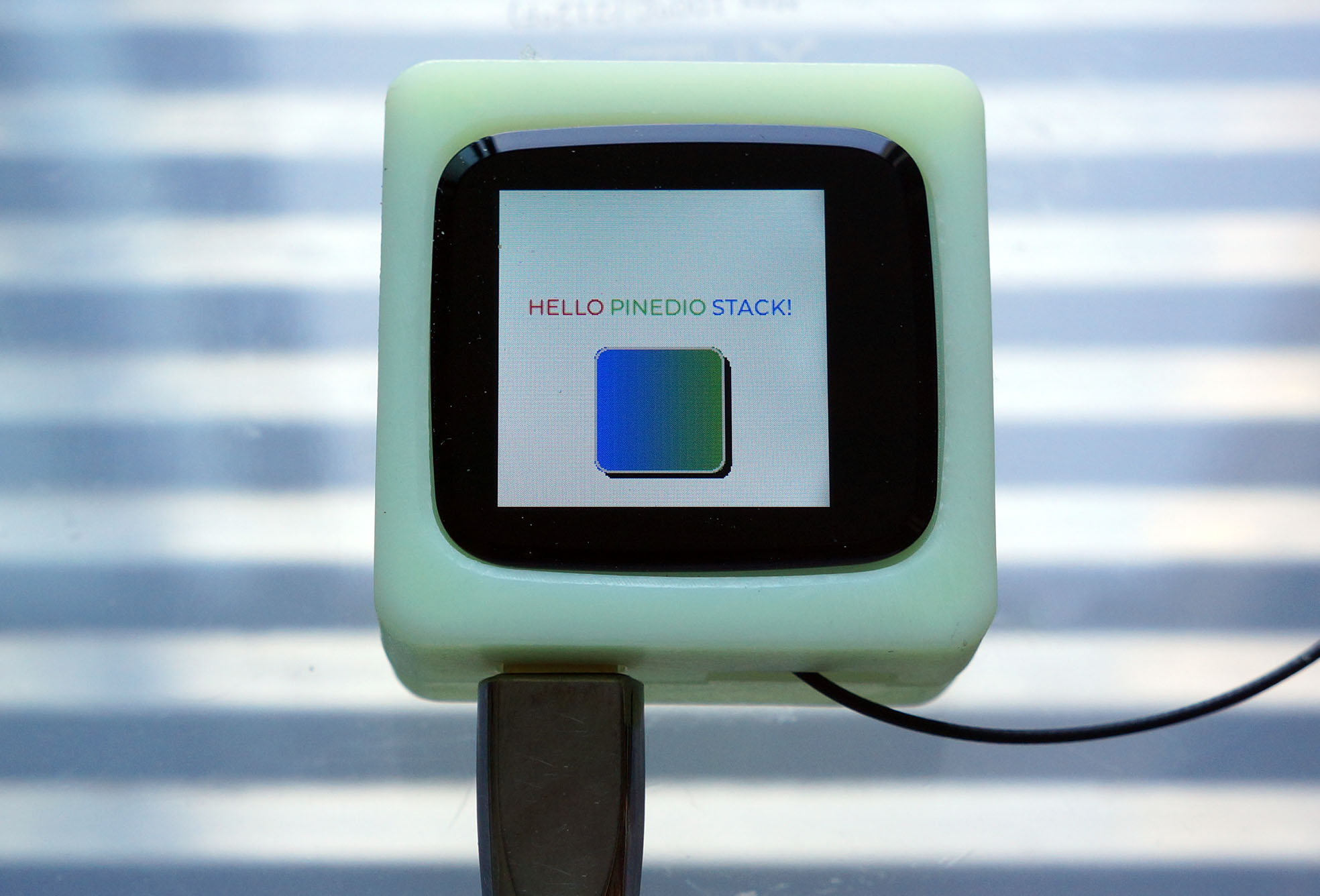
PineDio Stack BL604 is Pine64's newest microcontroller board, based on Bouffalo Lab's BL604 RISC-V + WiFi + Bluetooth LE SoC.
(Available any day now!)
PineDio Stack is packed chock-full of features...
-
ST7789 Colour LCD Display
(240 x 240 pixels)
-
CST816S Touch Panel
(Connected on I2C)
-
Semtech SX1262 LoRa Transceiver
(Works with LoRaWAN)
-
AT6558 GPS / GNSS Receiver
-
SGM40561 Power Management Unit
-
Heart Rate Sensor, Accelerometer, Compass, Vibrator
-
SPI Flash, JTAG Debugging Port, Push Button
-
2.4 GHz WiFi, Bluetooth LE
(Thanks to BL604)
Which makes it an incredible gadget for IoT Education!
Source code for Apache NuttX RTOS on PineDio Stack is here...
NuttX Build Config for PineDio Stack BL604...
To download, configure and build NuttX for PineDio Stack BL604...
mkdir nuttx
cd nuttx
git clone --recursive --branch pinedio https://github.com/lupyuen/incubator-nuttx nuttx
git clone --recursive --branch pinedio https://github.com/lupyuen/incubator-nuttx-apps apps
cd nuttx
./tools/configure.sh bl602evb:pinedio
makeAcording to the PineDio Stack Schematic...
The SPI Bus is shared by...
-
ST7789 Display Controller
-
Semtech SX1262 LoRa Transceiver
-
SPI Flash
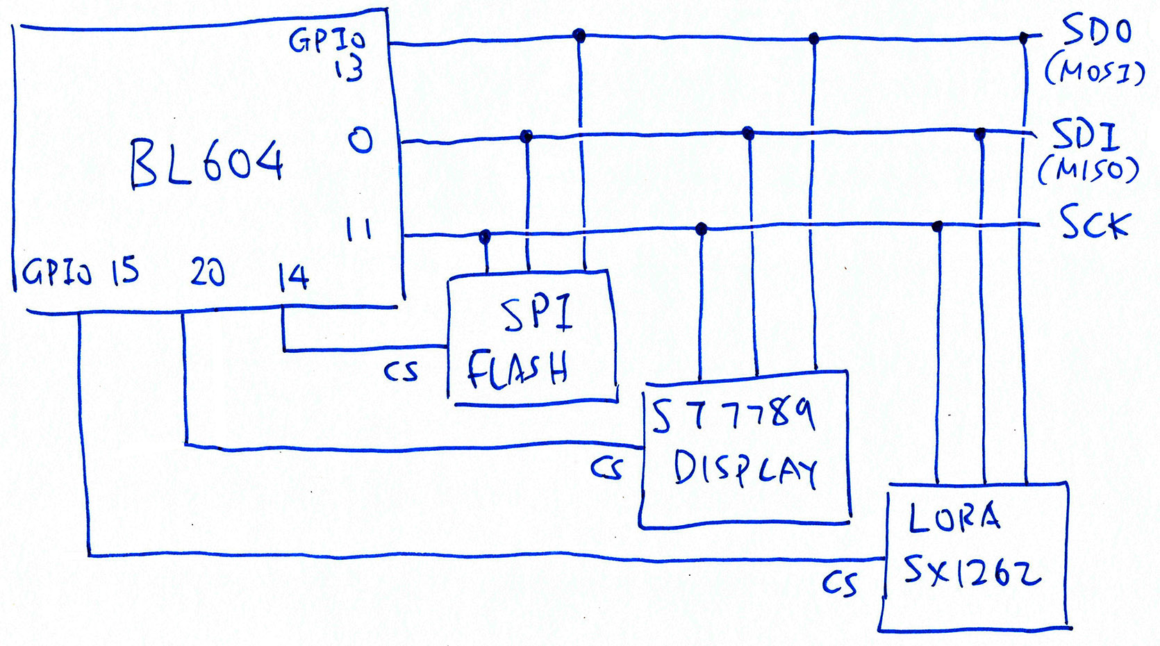
Here are the BL604 GPIO Numbers for the shared SPI Bus...
| Function | GPIO |
|---|---|
| SPI MOSI | 13 |
| SPI MISO | 0 |
| SPI SCK | 11 |
| SPI CS (Unused) | 8 |
To prevent crosstalk, we select each SPI Device by flipping its Chip Select Pin from High to Low...
| SPI Device | Device ID | Swap MISO/MOSI | Chip Select |
|---|---|---|---|
| ST7789 Display | 0x40000 | No | 20 |
| SX1262 Transceiver | 1 | Yes | 15 |
| SPI Flash | 2 | Yes | 14 |
| (Default Device) | -1 | Yes | 8 (Unused) |
NuttX auto-assigns 0x40000 as the SPI Device ID for ST7789 Display. (See this)
We assigned the other SPI Device IDs ourselves.
Device ID -1 is meant as a fallthrough to catch all SPI Devices that don't match the Device IDs. This also works for simple SPI setups where the Device ID is not needed.
According to BL602 Reference Manual (Table 3.1 "Pin Description", Page 26)...
-
GPIO 13 is MOSI
-
GPIO 0 is MISO
But due to a BL602 SPI quirk we need to Swap MISO and MOSI to get this behaviour. That's why the "Swap MISO / MOSI" column is marked "Yes" for SX1262 Transceiver and SPI Flash.
ST7789 Display Controller is wired differently...
-
ST7789 receives SPI Data on GPIO 0
-
ST7789 Data / Command Pin is connected on GPIO 13
(High for ST7789 Data, Low for ST7789 Commands)
The direction of SPI Data is flipped for ST7789. That's why the "Swap MISO / MOSI" column is marked "No" for ST7789 Display Controller.
We represent the above SPI Device Table in NuttX as a flat int array...
| SPI Device | Device ID | Swap MISO/MOSI | Chip Select |
|---|---|---|---|
| ST7789 Display | 0x40000 | 0 | 20 |
| SX1262 Transceiver | 1 | 1 | 15 |
| SPI Flash | 2 | 1 | 14 |
| (Default Device) | -1 | 1 | 8 |
Here's the source code...
#ifdef CONFIG_BL602_SPI0
/* SPI Device Table: SPI Device ID, Swap MISO/MOSI, Chip Select */

static const int32_t bl602_spi_device_table[] =
{
#ifdef BOARD_LCD_DEVID  /* ST7789 Display */
  BOARD_LCD_DEVID, BOARD_LCD_SWAP, BOARD_LCD_CS,
#endif  /* BOARD_LCD_DEVID */

#ifdef BOARD_SX1262_DEVID  /* LoRa SX1262 */
  BOARD_SX1262_DEVID, BOARD_SX1262_SWAP, BOARD_SX1262_CS,
#endif  /* BOARD_SX1262_DEVID */

#ifdef BOARD_FLASH_DEVID  /* SPI Flash */
  BOARD_FLASH_DEVID, BOARD_FLASH_SWAP, BOARD_FLASH_CS,
#endif  /* BOARD_FLASH_DEVID */

  /* Must end with Default SPI Device */

  -1, 1, BOARD_SPI_CS,  /* Swap MISO/MOSI */
};
#endif /* CONFIG_BL602_SPI0 */The columns of the SPI Device Table...
/* Columns in the SPI Device Table */

#define DEVID_COL 0  /* SPI Device ID */
#define SWAP_COL  1  /* 1 if MISO/MOSI should be swapped, else 0 */
#define CS_COL    2  /* SPI Chip Select Pin */
#define NUM_COLS 3 /* Number of columns in SPI Device Table */Here are the functions for accessing the SPI Device Table...
-
bl602_spi_get_device: Lookup a device in the SPI Device Table
-
bl602_spi_deselect_devices: Deselect all devices in the SPI Device Table
-
bl602_spi_validate_devices: Validate the devices in the SPI Device Table
The SPI Device Table above refers to the following Pin Definitions...
/* SPI for PineDio Stack: Chip Select (unused), MOSI, MISO, SCK */

#define BOARD_SPI_CS   (GPIO_INPUT | GPIO_PULLUP | GPIO_FUNC_SPI | GPIO_PIN8)  /* Unused */
#define BOARD_SPI_MOSI (GPIO_INPUT | GPIO_PULLUP | GPIO_FUNC_SPI | GPIO_PIN13)
#define BOARD_SPI_MISO (GPIO_INPUT | GPIO_PULLUP | GPIO_FUNC_SPI | GPIO_PIN0)
#define BOARD_SPI_CLK  (GPIO_INPUT | GPIO_PULLUP | GPIO_FUNC_SPI | GPIO_PIN11)

#ifdef CONFIG_LCD_ST7789
/* ST7789 for PineDio Stack: Chip Select, Reset and Backlight */

#define BOARD_LCD_DEVID SPIDEV_DISPLAY(0)  /* SPI Device ID: 0x40000 */
#define BOARD_LCD_SWAP  0    /* Don't swap MISO/MOSI */
#define BOARD_LCD_BL_INVERT  /* Backlight is active when Low */
#define BOARD_LCD_CS  (GPIO_OUTPUT | GPIO_PULLUP | GPIO_FUNC_SWGPIO | GPIO_PIN20)
#define BOARD_LCD_RST (GPIO_OUTPUT | GPIO_PULLUP | GPIO_FUNC_SWGPIO | GPIO_PIN3)
#define BOARD_LCD_BL  (GPIO_OUTPUT | GPIO_PULLUP | GPIO_FUNC_SWGPIO | GPIO_PIN21)
#endif  /* CONFIG_LCD_ST7789 */

/* SX1262 for PineDio Stack: Chip Select */

#define BOARD_SX1262_DEVID 1  /* SPI Device ID */
#define BOARD_SX1262_SWAP  1  /* Swap MISO/MOSI */
#define BOARD_SX1262_CS (GPIO_OUTPUT | GPIO_PULLUP | GPIO_FUNC_SWGPIO | GPIO_PIN15)

/* SPI Flash for PineDio Stack: Chip Select */

#define BOARD_FLASH_DEVID 2  /* SPI Device ID */
#define BOARD_FLASH_SWAP  1  /* Swap MISO/MOSI */
#define BOARD_FLASH_CS (GPIO_OUTPUT | GPIO_PULLUP | GPIO_FUNC_SWGPIO | GPIO_PIN14)BL602 NuttX SPI Driver looks up the SPI Device Table to 1️⃣ Swap MISO and MOSI Pins 2️⃣ Flip the Chip Select Pins. This is how we select and deselect each SPI Device...
//  Enable/disable the SPI chip select
static void bl602_spi_select(struct spi_dev_s *dev, uint32_t devid,
                             bool selected)
{
  const int32_t *spidev;

  spiinfo("devid: %lu, CS: %s\n", devid, selected ? "select" : "free");

  /* get device from SPI Device Table */

  spidev = bl602_spi_get_device(devid);
  DEBUGASSERT(spidev != NULL);

  /* swap MISO and MOSI if needed */

  if (selected)
    {
      bl602_swap_spi_0_mosi_with_miso(spidev[SWAP_COL]);
    }

  /* set Chip Select */

  bl602_gpiowrite(spidev[CS_COL], !selected);

#ifdef CONFIG_SPI_CMDDATA
  /* revert MISO and MOSI from GPIO Pins to SPI Pins */

  if (!selected)
    {
      bl602_configgpio(BOARD_SPI_MISO);
      bl602_configgpio(BOARD_SPI_MOSI);
    }
#endif
}bl602_spi_select is called after locking the SPI Bus.
NuttX RTOS uses MISO as the ST7789 Data / Command Pin ... But ST7789 is wired "backwards" on PineDio Stack BL604! We use MOSI as the ST7789 Data / Command Pin instead.
Here's how we flip the ST7789 Data / Command pin depending on MISO / MOSI Swap...
#ifdef CONFIG_SPI_CMDDATA
static int bl602_spi_cmddata(struct spi_dev_s *dev,
                              uint32_t devid, bool cmd)
{
  spiinfo("devid: %" PRIu32 " CMD: %s\n", devid, cmd ? "command" :
          "data");

  if (devid == SPIDEV_DISPLAY(0))
    {
      const int32_t *spidev;
      gpio_pinset_t dc;
      gpio_pinset_t gpio;
      int ret;

      /* get device from SPI Device Table */

      spidev = bl602_spi_get_device(devid);
      DEBUGASSERT(spidev != NULL);

      /* if MISO/MOSI are swapped, DC is MISO, else MOSI */

      dc = spidev[SWAP_COL] ? BOARD_SPI_MISO : BOARD_SPI_MOSI;

      /* reconfigure DC from SPI Pin to GPIO Pin */

      gpio = (dc & GPIO_PIN_MASK)
             | GPIO_OUTPUT | GPIO_PULLUP | GPIO_FUNC_SWGPIO;
      ret = bl602_configgpio(gpio);
      if (ret < 0)
        {
          spierr("Failed to configure MISO as GPIO\n");
          DEBUGPANIC();

          return ret;
        }

      /* set DC to high (data) or low (command) */

      bl602_gpiowrite(gpio, !cmd);

      return OK;
    }

  spierr("SPI cmddata not supported\n");
  DEBUGPANIC();

  return -ENODEV;
}
#endifAt NuttX Startup, we deselect all SPI Devices ... By flipping their Chip Select Pins high...
static void bl602_spi_init(struct spi_dev_s *dev)
{
  struct bl602_spi_priv_s *priv = (struct bl602_spi_priv_s *)dev;
  const struct bl602_spi_config_s *config = priv->config;

  /* Initialize the SPI semaphore that enforces mutually exclusive access */

  nxsem_init(&priv->exclsem, 0, 1);

  bl602_configgpio(BOARD_SPI_CS);
  bl602_configgpio(BOARD_SPI_MOSI);
  bl602_configgpio(BOARD_SPI_MISO);
  bl602_configgpio(BOARD_SPI_CLK);

  /* set master mode */

  bl602_set_spi_0_act_mode_sel(1);

  /* swap MOSI with MISO to be consistent with BL602 Reference Manual */

  bl602_swap_spi_0_mosi_with_miso(1);

  /* spi cfg  reg:
   * cr_spi_deg_en 1
   * cr_spi_m_cont_en 0
   * cr_spi_byte_inv 0
   * cr_spi_bit_inv 0
   */

  modifyreg32(BL602_SPI_CFG, SPI_CFG_CR_M_CONT_EN
              | SPI_CFG_CR_BYTE_INV | SPI_CFG_CR_BIT_INV,
              SPI_CFG_CR_DEG_EN);

  /* disable rx ignore */

  modifyreg32(BL602_SPI_CFG, SPI_CFG_CR_RXD_IGNR_EN, 0);

  bl602_spi_setfrequency(dev, config->clk_freq);
  bl602_spi_setbits(dev, 8);
  bl602_spi_setmode(dev, config->mode);

  /* spi fifo clear */

  modifyreg32(BL602_SPI_FIFO_CFG_0, SPI_FIFO_CFG_0_RX_CLR
              | SPI_FIFO_CFG_0_TX_CLR, 0);

  /* deselect all spi devices */

  bl602_spi_deselect_devices();
}Will ST7789 Display play nice with LoRa SX1262 on PineDio Stack BL604? Yep SX1262 works OK on the Shared SPI Bus!
PineDio Stack boots and renders a Pink Screen...
gpio_pin_register: Registering /dev/gpio0
gpio_pin_register: Registering /dev/gpio1
gpint_enable: Disable the interrupt
gpio_pin_register: Registering /dev/gpio2
bl602_gpio_set_intmod: ****gpio_pin=115, int_ctlmod=1, int_trgmod=0
spi_test_driver_register: devpath=/dev/spitest0, spidev=0
st7789_sleep: sleep: 0
st7789_sendcmd: cmd: 0x11
st7789_sendcmd: OK
st7789_bpp: bpp: 16
st7789_sendcmd: cmd: 0x3a
st7789_sendcmd: OK
st7789_setorientation:
st7789_sendcmd: cmd: 0x36
st7789_sendcmd: OK
st7789_display: on: 1
st7789_sendcmd: cmd: 0x29
st7789_sendcmd: OK
st7789_sendcmd: cmd: 0x21
st7789_sendcmd: OK
st7789_fill: color: 0xaaaa
st7789_sendcmd: cmd: 0x2b
st7789_sendcmd: OK
st7789_sendcmd: cmd: 0x2a
st7789_sendcmd: OK
st7789_sendcmd: cmd: 0x2c
st7789_sendcmd: OK
board_lcd_getdev: SPI port 0 bound to LCD 0
st7789_getplaneinfo: planeno: 0 bpp: 16
We run the spi_test2 app to test SX1262...
NuttShell (NSH) NuttX-10.2.0-RC0
nsh>
nsh> ?
help usage:  help [-v] [<cmd>]

  ?      cat    help   ls     uname

Builtin Apps:
  tinycbor_test            spi_test                 nsh
  lorawan_test             timer                    sensortest
  sx1262_test              bl602_adc_test           ikea_air_quality_sensor
  bas                      spi_test2                gpio
  sh                       getprime
  lvgldemo                 hello
nsh> spi_test2
spi_test_driver_open:
gpout_write: Writing 0
spi_test_driver_write: buflen=2
spi_test_driver_configspi:
spi_test_driver_read: buflen=256
gpout_write: Writing 1
Get Status: received
  a2 22
SX1262 Status is 2
gpout_write: Writing 0
spi_test_driver_write: buflen=5
spi_test_driver_configspi:
spi_test_driver_read: buflen=256
gpout_write: Writing 1
Read Register 8: received
  a2 a2 a2 a2 80
SX1262 Register 8 is 0x80
SX1262 returns Register Value 0x80, which is correct!
Then we run the LVGL Demo App...
spi_test_driver_close:
nsh> lvgldemo
fbdev_init: Failed to open /dev/fb0: 2
st7789_getvideoinfo: fmt: 11 xres: 240 yres: 240 nplanes: 1
lcddev_init: VideoInfo:
        fmt: 11
        xres: 240
        yres: 240
        nplanes: 1
lcddev_init: PlaneInfo (plane 0):
        bpp: 16
st7789_putarea: row_start: 0 row_end: 19 col_start: 0 col_end: 239
st7789_sendcmd: cmd: 0x2b
st7789_sendcmd: OK
st7789_sendcmd: cmd: 0x2a
st7789_sendcmd: OK
st7789_sendcmd: cmd: 0x2c
st7789_sendcmd: OK
st7789_putarea: row_start: 20 row_end: 39 col_start: 0 col_end: 239
st7789_sendcmd: cmd: 0x2b
st7789_sendcmd: OK
st7789_sendcmd: cmd: 0x2a
st7789_sendcmd: OK
st7789_sendcmd: cmd: 0x2c
st7789_sendcmd: OK
st7789_putarea: row_start: 40 row_end:59 col_start: 0 col_end: 239
st7789_sendcmd: cmd: 0x2b
st7789_sendcmd: OK
st7789_sendcmd: cmd: 0x2a
st7789_sendcmd: OK
st7789_sendcmd: cmd: 0x2c
st7789_sendcmd: OK
st7789_putarea: row_start: 60 row_end: 79 col_start: 0 col_end: 239
st7789_sendcmd: cmd: 0x2b
st7789_sendcmd: OK
st7789_sendcmd: cmd: 0x2a
st7789_sendcmd: OK
st7789_sendcmd: cmd: 0x2c
st7789_sendcmd: OK
st7789_putarea: row_start: 80 row_end: 99 col_start: 0 col_end: 239
st7789_sendcmd: cmd: 0x2b
st7789_sendcmd: OK
st7789_sendcmd: cmd: 0x2a
st7789_sendcmd: OK
st7789_sendcmd: cmd: 0x2c
st7789_sendcmd: OK
st7789_putarea: row_start: 100 row_end: 119 col_start: 0 col_end: 239
st7789_sendcmd: cmd: 0x2b
st7789_sendcmd: OK
st7789_sendcmd: cmd: 0x2a
st7789_sendcmd: OK
st7789_sendcmd: cmd: 0x2c
st7789_sendcmd: OK
st7789_putarea: row_start: 120 row_end: 139 col_start: 0 col_end: 239
st7789_sendcmd: cmd: 0x2b
st7789_sendcmd: OK
st7789_sendcmd: cmd: 0x2a
st7789_sendcmd: OK
st7789_sendcmd: cmd: 0x2c
st7789_sendcmd: OK
st7789_putarea: row_start: 140 row_end: 159 col_start: 0 col_end: 239
st7789_sendcmd: cmd: 0x2b
st7789_sendcmd: OK
st7789_sendcmd: cmd: 0x2a
st7789_sendcmd: OK
st7789_sendcmd: cmd: 0x2c
st7789_sendcmd: OK
st7789_putarea: row_start: 160 row_end: 179 col_start: 0 col_end: 239
st7789_sendcmd: cmd: 0x2b
st7789_sendcmd: OK
st7789_sendcmd: cmd: 0x2a
st7789_sendcmd: OK
st7789_sendcmd: cmd: 0x2c
st7789_sendcmd: OK
st7789_putarea: row_start: 180 row_end: 199 col_start: 0 col_end: 239
st7789_sendcmd: cmd: 0x2b
st7789_sendcmd: OK
st7789_sendcmd: cmd: 0x2a
st7789_sendcmd: OK
st7789_sendcmd: cmd: 0x2c
st7789_sendcmd: OK
st7789_putarea: row_start: 200 row_end: 219 col_start: 0 col_end: 239
st7789_sendcmd: cmd: 0x2b
st7789_sendcmd: OK
st7789_sendcmd: cmd: 0x2a
st7789_sendcmd: OK
st7789_sendcmd: cmd: 0x2c
st7789_sendcmd: OK
st7789_putarea: row_start: 220 row_end: 239 col_start: 0 col_end: 239
st7789_sendcmd: cmd: 0x2b
st7789_sendcmd: OK
st7789_sendcmd: cmd: 0x2a
st7789_sendcmd: OK
st7789_sendcmd: cmd: 0x2c
st7789_sendcmd: OK
monitor_cb: 57600 px refreshed in 1110 ms
Which renders the LVGL Demo Screen on ST7789 correctly!
There's a potential Race Condition if we use the SX1262 Driver concurrently with the ST7789 Driver...
-
During LoRa Transmission, SX1262 Driver calls
ioctl()to flip SX1262 Chip Select to Low -
SX1262 Driver calls SPI Test Driver
/dev/spitest0, which locks (SPI_LOCK) and selects (SPI_SELECT) the SPI Bus (with SPI Device ID 0) -
Note that the calls to
ioctl()andSPI_LOCK / SPI_SELECTare NOT Atomic -
If the ST7789 Driver is active between the calls to
ioctl()andSPI_LOCK / SPI_SELECT, both SX1262 Chip Select and ST7789 Chip Select will be flipped to Low -
This might transmit garbage to SX1262
To solve this problem, we will register a new SPI Test Driver /dev/spitest1 with SPI Device ID 1.
The LoRa Driver will then access /dev/spitest1, which will SPI_LOCK and SPI_SELECT the SPI Bus (with SPI Device ID 1).
Since the SPI Device ID is 1, SPI_SELECT will flip the SX1262 Chip Select to Low.
BL602 / BL604 talks to ST7789 Display at SPI Mode 1 or 3 ... Depends whether MISO / MOSI are swapped
#ifdef CONFIG_BL602_SPI0
#include "../boards/risc-v/bl602/bl602evb/include/board.h"
#endif  /* CONFIG_BL602_SPI0 */

#ifdef CONFIG_LCD_ST7789

/****************************************************************************
 * Pre-processor Definitions
 ****************************************************************************/

/* Verify that all configuration requirements have been met */

#ifdef CONFIG_BL602_SPI0
#  if defined(BOARD_LCD_SWAP) && BOARD_LCD_SWAP == 0  /* If MISO/MOSI not swapped... */
#    warning Using SPI Mode 1 for ST7789 on BL602 (MISO/MOSI not swapped)
#    define CONFIG_LCD_ST7789_SPIMODE SPIDEV_MODE1  /* SPI Mode 1: Workaround for BL602 */
#  else
#    warning Using SPI Mode 3 for ST7789 on BL602 (MISO/MOSI swapped)
#    define CONFIG_LCD_ST7789_SPIMODE SPIDEV_MODE3  /* SPI Mode 3: Workaround for BL602 */
#  endif /* BOARD_LCD_SWAP */
#else
#  ifndef CONFIG_LCD_ST7789_SPIMODE
#    define CONFIG_LCD_ST7789_SPIMODE SPIDEV_MODE0
#  endif /* CONFIG_LCD_ST7789_SPIMODE */
#endif /* CONFIG_BL602_SPI0 */ST7789 Display runs OK at SPI Frequency 4 MHz. Maybe we can go higher?
CONFIG_LCD_ST7789_FREQUENCY=4000000
LVGL Test App is here...
To run the app, enter this at the NuttX Shell...
lvgltestHere's the code that renders the screen...
//  Create the LVGL Widgets that will be rendered on the display
static void create_widgets(void)
{
  //  Get the Active Screen
  lv_obj_t *screen = lv_scr_act();

  //  Create a Label Widget
  lv_obj_t *label = lv_label_create(screen, NULL);

  //  Wrap long lines in the label text
  lv_label_set_long_mode(label, LV_LABEL_LONG_BREAK);

  //  Interpret color codes in the label text
  lv_label_set_recolor(label, true);

  //  Center align the label text
  lv_label_set_align(label, LV_LABEL_ALIGN_CENTER);

  //  Set the label text and colors
  lv_label_set_text(
    label,
    "#ff0000 HELLO# "    //  Red Text
    "#00ff00 PINEDIO# "  //  Green Text
    "#0000ff STACK!# "   //  Blue Text
  );

  //  Set the label width
  lv_obj_set_width(label, 200);

  //  Align the label to the center of the screen, shift 30 pixels up
  lv_obj_align(label, NULL, LV_ALIGN_CENTER, 0, -30);

#ifdef CONFIG_USE_LV_CANVAS  //  LVGL Canvas Demo
  //  Create the Canvas
  lv_obj_t *canvas = lv_canvas_create(screen, NULL);

  //  Set the Canvas Buffer (Warning: Might take a lot of RAM!)
  static lv_color_t cbuf[LV_CANVAS_BUF_SIZE_TRUE_COLOR(CANVAS_WIDTH, CANVAS_HEIGHT)];
  lv_canvas_set_buffer(canvas, cbuf, CANVAS_WIDTH, CANVAS_HEIGHT, LV_IMG_CF_TRUE_COLOR);

  //  Align the canvas to the center of the screen, shift 50 pixels down
  lv_obj_align(canvas, NULL, LV_ALIGN_CENTER, 0, 50);

  //  Fill the canvas with white
  lv_canvas_fill_bg(canvas, LV_COLOR_WHITE, LV_OPA_TRANSP);

  //  Create a Rounded Rectangle
  lv_draw_rect_dsc_t rect_dsc;
  lv_draw_rect_dsc_init(&rect_dsc);
  rect_dsc.radius = 10;            //  Corner Radius
  rect_dsc.bg_opa = LV_OPA_COVER;  //  Opacity: Opaque
  rect_dsc.bg_grad_dir   = LV_GRAD_DIR_HOR;  //  Gradient Direction: Horizontal
  rect_dsc.bg_color      = LV_COLOR_BLUE;    //  From Blue
  rect_dsc.bg_grad_color = LV_COLOR_GREEN;   //  To Green
  rect_dsc.border_width  = 2;  //  Border Width
  rect_dsc.border_opa    = LV_OPA_90;        //  Border Opacity: 90%
  rect_dsc.border_color  = LV_COLOR_SILVER;  //  Border Color
  rect_dsc.shadow_width  = 5;  //  Shadow Width
  rect_dsc.shadow_ofs_x  = 5;  //  Shadow Offset X
  rect_dsc.shadow_ofs_y  = 5;  //  Shadow Offset Y

  //  Draw the Rounded Rectangle to the canvas
  lv_canvas_draw_rect(canvas, 0, 0, 95, 95, &rect_dsc);
#endif  //  CONFIG_USE_LV_CANVAS

#ifdef CONFIG_EXAMPLES_LVGLTEST_MESSAGEBOX  //  LVGL Message Box Demo
  //  Create a Message Box Widget
  lv_obj_t *msgbox = lv_msgbox_create(screen, NULL);

  //  Set the Message Box Text
  lv_msgbox_set_text(msgbox, "Hello PineDio Stack!");

  //  Define the Message Box Buttons
  static const char *btns[] = {"Cancel", "OK", ""};

  //  Add the buttons to the Message Box
  lv_msgbox_add_btns(msgbox, btns);
#endif  //  CONFIG_EXAMPLES_LVGLTEST_MESSAGEBOX
}To render our own text and graphics, edit this source file and change the code above...
apps/examples/lvgltest/lvgltest.c
To run the app, enter this at the NuttX Shell...
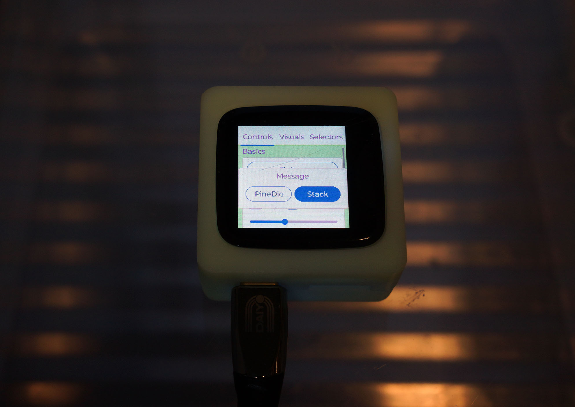
lvgldemoTo change the message in LVGL Demo App, edit apps/examples/lvgldemo/lv_demos/src/lv_demo_widgets/lv_demo_widgets.c...
static void controls_create(lv_obj_t * parent)
{
    lv_page_set_scrl_layout(parent, LV_LAYOUT_PRETTY_TOP);

    lv_disp_size_t disp_size = lv_disp_get_size_category(NULL);
    lv_coord_t grid_w = lv_page_get_width_grid(parent, disp_size <= LV_DISP_SIZE_SMALL ? 1 : 2, 1);

#if LV_DEMO_WIDGETS_SLIDESHOW == 0
    static const char * btns[] = {"PineDio", "Stack", ""};

    lv_obj_t * m = lv_msgbox_create(lv_scr_act(), NULL);
    lv_msgbox_add_btns(m, btns);
    lv_obj_t * btnm = lv_msgbox_get_btnmatrix(m);
    lv_btnmatrix_set_btn_ctrl(btnm, 1, LV_BTNMATRIX_CTRL_CHECK_STATE);
#endifTo test LoRa on PineDio Stack, edit sx1262_test_main.c at...
apps/examples/sx1262_test/sx1262_test_main.c
And update the LoRa Parameters...
LoRaWAN works OK on Shared SPI Bus yay! PineDio Stack connects to LoRaWAN Gateway (ChirpStack) and sends data packets.
(Internal Temperature Sensor on ADC works OK too)
Remember to disable all Info Logging because it affects the LoRaWAN Timers.
Here's how we set the LoRaWAN Parameters...
NuttShell (NSH) NuttX-10.2.0-RC0
nsh> lorawan_test
init_entropy_pool
offset = 2228
temperature = 31.600670 Celsius
offset = 2228
temperature = 31.084742 Celsius
offset = 2228
temperature = 32.890495 Celsius
offset = 2228
temperature = 33.535404 Celsius

###### ===================================== ######

Application name   : lorawan_test
Application version: 1.2.0
GitHub base version: 5.0.0

###### ===================================== ######

init_event_queue
TimerInit:     0x4201c750
callout_handler: lock
TimerInit:     0x4201c76c
TimerInit:     0x4201c788
TimerInit:     0x4201c804
TimerInit:     0x4201c8b8
TimerInit:     0x4201c8d4
TimerInit:     0x4201c8f0
TimerInit:     0x4201c90c
TODO: RtcGetCalendarTime
TODO: SX126xReset
init_gpio
DIO1 pintype before=5
init_gpio: change DIO1 to Trigger GPIO Interrupt on Rising Edge
gpio_ioctl: Requested pintype 8, but actual pintype 5
DIO1 pintype after=5
Starting process_dio1
process_dio1 started
process_dio1: event=0x4201b878
init_spi
SX126xSetTxParams: power=22, rampTime=7
SX126xSetPaConfig: paDutyCycle=4, hpMax=7, deviceSel=0, paLut=1
TimerInit:     0x4201b850
TimerInit:     0x4201b7bc
RadioSetModem
RadioSetModem
RadioSetPublicNetwork: public syncword=3444
RadioSleep
DIO1 add event
TODO: EepromMcuReadBuffer
TODO: EepromMcuReadBuffer
TODO: EepromMcuReadBuffer
TODO: EepromMcuReadBuffer
TODO: EepromMcuReadBuffer
TODO: EepromMcuReadBuffer
TODO: EepromMcuReadBuffer
TODO: EepromMcuReadBuffer
RadioSetModem
RadioSetPublicNetwork: public syncword=3444
DevEui      : 4B-C1-5E-E7-37-7B-B1-5B
JoinEui     : 00-00-00-00-00-00-00-00
Pin         : 00-00-00-00

TimerInit:     0x4201c3a8
TimerInit:     0x4201c3c4
TimerInit:     0x4201c288
TODO: RtcGetCalendarTime
TODO: RtcBkupRead
TODO: RtcBkupRead
RadioSetChannel: freq=923200000
RadioSetTxConfig: modem=1, power=13, fdev=0, bandwidth=0, datarate=10, coderate=      1, preambleLen=8, fixLen=0, crcOn=1, freqHopOn=0, hopPeriod=0, iqInverted=0, tim      eout=4000
RadioSetTxConfig: SpreadingFactor=10, Bandwidth=4, CodingRate=1, LowDatarateOpti      mize=0, PreambleLength=8, HeaderType=0, PayloadLength=255, CrcMode=1, InvertIQ=0
RadioStandby
RadioSetModem
SX126xSetTxParams: power=13, rampTime=7
SX126xSetPaConfig: paDutyCycle=4, hpMax=7, deviceSel=0, paLut=1
SecureElementRandomNumber: 0xa8c2a6e7
RadioSend: size=23
00 00 00 00 00 00 00 00 00 5b b1 7b 37 e7 5e c1 4b e7 a6 80 b1 e0 e4
RadioSend: PreambleLength=8, HeaderType=0, PayloadLength=23, CrcMode=1, InvertIQ      =0
TimerStop:     0x4201b850
TimerStart2:   0x4201b850, 4000 ms
callout_reset: evq=0x42013250, ev=0x4201b850

###### =========== MLME-Request ============ ######
######               MLME_JOIN               ######
###### ===================================== ######
STATUS      : OK
StartTxProcess
TimerInit:     0x42015b7c
TimerSetValue: 0x42015b7c, 42249 ms
OnTxTimerEvent: timeout in 42249 ms, event=0
TimerStop:     0x42015b7c
TimerSetValue: 0x42015b7c, 42249 ms
TimerStart:    0x42015b7c
TimerStop:     0x42015b7c
TimerStart2:   0x42015b7c, 42249 ms
callout_reset: evq=0x42013250, ev=0x42015b7c
handle_event_queue
handle_event_queue: ev=0x4201b878
RadioOnDioIrq
RadioIrqProcess
RadioOnDioIrq
RadioIrqProcess
DIO1 add event
handle_event_queue: ev=0x4201b878
RadioOnDioIrq
RadioIrqProcess
IRQ_TX_DONE
TimerStop:     0x4201b850
TODO: RtcGetCalendarTime
TODO: RtcBkupRead
RadioOnDioIrq
RadioIrqProcess
RadioSleep
DIO1 add event
TimerSetValue: 0x4201c76c, 4988 ms
TimerStart:    0x4201c76c
TimerStop:     0x4201c76c
TimerStart2:   0x4201c76c, 4988 ms
callout_reset: evq=0x42013250, ev=0x4201c76c
TimerSetValue: 0x4201c788, 5988 ms
TimerStart:    0x4201c788
TimerStop:     0x4201c788
TimerStart2:   0x4201c788, 5988 ms
callout_reset: evq=0x42013250, ev=0x4201c788
TODO: RtcGetCalendarTime
handle_event_queue: ev=0x4201b878
RadioOnDioIrq
RadioIrqProcess
RadioOnDioIrq
RadioIrqProcess
callout_handler: unlock
callout_handler: evq=0x42013250, ev=0x4201c76c
callout_handler: lock
handle_event_queue: ev=0x4201c76c
TimerStop:     0x4201c76c
RadioStandby
RadioSetChannel: freq=923200000
RadioSetRxConfig
RadioStandby
RadioSetModem
RadioSetRxConfig done
RadioRx
TimerStop:     0x4201b7bc
TimerStart2:   0x4201b7bc, 3000 ms
callout_reset: evq=0x42013250, ev=0x4201b7bc
RadioOnDioIrq
RadioIrqProcess
DIO1 add event
handle_event_queue: ev=0x4201b878
RadioOnDioIrq
RadioIrqProcess
IRQ_PREAMBLE_DETECTED
RadioOnDioIrq
RadioIrqProcess
DIO1 add event
handle_event_queue: ev=0x4201b878
RadioOnDioIrq
RadioIrqProcess
IRQ_HEADER_VALID
RadioOnDioIrq
RadioIrqProcess
DIO1 add event
handle_event_queue: ev=0x4201b878
RadioOnDioIrq
RadioIrqProcess
IRQ_RX_DONE
TimerStop:     0x4201b7bc
RadioOnDioIrq
RadioIrqProcess
RadioSleep
DIO1 add event
TimerStop:     0x4201c788
OnTxData

###### =========== MLME-Confirm ============ ######
STATUS      : OK
OnJoinRequest
###### ===========   JOINED     ============ ######

OTAA

DevAddr     :  01097710


DATA RATE   : DR_2

TODO: EepromMcuWriteBuffer
TODO: EepromMcuWriteBuffer
TODO: EepromMcuWriteBuffer
TODO: EepromMcuWriteBuffer
TODO: EepromMcuWriteBuffer
TODO: EepromMcuWriteBuffer
UplinkProcess
PrepareTxFrame: Transmit to LoRaWAN: Hi NuttX (9 bytes)
PrepareTxFrame: status=0, maxSize=11, currentSize=11
LmHandlerSend: Data frame
TODO: RtcGetCalendarTime
TODO: RtcBkupRead
RadioSetChannel: freq=923200000
RadioSetTxConfig: modem=1, power=13, fdev=0, bandwidth=0, datarate=9, coderate=1      , preambleLen=8, fixLen=0, crcOn=1, freqHopOn=0, hopPeriod=0, iqInverted=0, time      out=4000
RadioSetTxConfig: SpreadingFactor=9, Bandwidth=4, CodingRate=1, LowDatarateOptim      ize=0, PreambleLength=8, HeaderType=0, PayloadLength=128, CrcMode=1, InvertIQ=0
RadioStandby
RadioSetModem
SX126xSetTxParams: power=13, rampTime=7
SX126xSetPaConfig: paDutyCycle=4, hpMax=7, deviceSel=0, paLut=1
RadioSend: size=22
40 10 77 09 01 00 01 00 01 a5 12 b3 cc a2 27 27 57 dc c3 a7 eb ae
RadioSend: PreambleLength=8, HeaderType=0, PayloadLength=22, CrcMode=1, InvertIQ      =0
TimerStop:     0x4201b850
TimerStart2:   0x4201b850, 4000 ms
callout_reset: evq=0x42013250, ev=0x4201b850

###### =========== MCPS-Request ============ ######
######           MCPS_UNCONFIRMED            ######
###### ===================================== ######
STATUS      : OK
PrepareTxFrame: Transmit OK
handle_event_queue: ev=0x4201b878
RadioOnDioIrq
RadioIrqProcess
RadioOnDioIrq
RadioIrqProcess
DIO1 add event
handle_event_queue: ev=0x4201b878
RadioOnDioIrq
RadioIrqProcess
IRQ_TX_DONE
TimerStop:     0x4201b850
TODO: RtcGetCalendarTime
TODO: RtcBkupRead
RadioOnDioIrq
RadioIrqProcess
RadioSleep
DIO1 add event
TimerSetValue: 0x4201c76c, 980 ms
TimerStart:    0x4201c76c
TimerStop:     0x4201c76c
TimerStart2:   0x4201c76c, 980 ms
callout_reset: evq=0x42013250, ev=0x4201c76c
TimerSetValue: 0x4201c788, 1988 ms
TimerStart:    0x4201c788
TimerStop:     0x4201c788
TimerStart2:   0x4201c788, 1988 ms
callout_reset: evq=0x42013250, ev=0x4201c788
TODO: RtcGetCalendarTime
handle_event_queue: ev=0x4201b878
RadioOnDioIrq
RadioIrqProcess
RadioOnDioIrq
RadioIrqProcess
callout_handler: unlock
callout_handler: evq=0x42013250, ev=0x4201c76c
callout_handler: lock
handle_event_queue: ev=0x4201c76c
TimerStop:     0x4201c76c
RadioStandby
RadioSetChannel: freq=923200000
RadioSetRxConfig
RadioStandby
RadioSetModem
RadioSetRxConfig done
RadioRx
TimerStop:     0x4201b7bc
TimerStart2:   0x4201b7bc, 3000 ms
callout_reset: evq=0x42013250, ev=0x4201b7bc
RadioOnDioIrq
RadioIrqProcess
DIO1 add event
handle_event_queue: ev=0x4201b878
RadioOnDioIrq
RadioIrqProcess
IRQ_RX_TX_TIMEOUT
TimerStop:     0x4201b7bc
RadioOnDioIrq
RadioIrqProcess
RadioSleep
DIO1 add event
TimerStop:     0x4201c788
TimerStop:     0x4201c750
OnTxData

###### =========== MCPS-Confirm ============ ######
STATUS      : OK

###### =====   UPLINK FRAME        1   ===== ######

CLASS       : A

TX PORT     : 1
TX DATA     : UNCONFIRMED
48 69 20 4E 75 74 74 58 00

DATA RATE   : DR_3
U/L FREQ    : 923200000
TX POWER    : 0
CHANNEL MASK: 0003

TODO: EepromMcuWriteBuffer
TODO: EepromMcuWriteBuffer
UplinkProcess
handle_event_queue: ev=0x4201b878
RadioOnDioIrq
RadioIrqProcess
RadioOnDioIrq
RadioIrqProcess
UplinkProcess
callout_handler: unlock
callout_handler: evq=0x42013250, ev=0x42015b7c
callout_handler: lock
handle_event_queue: ev=0x42015b7c
OnTxTimerEvent: timeout in 42249 ms, event=0x42015b7c
TimerStop:     0x42015b7c
TimerSetValue: 0x42015b7c, 42249 ms
TimerStart:    0x42015b7c
TimerStop:     0x42015b7c
TimerStart2:   0x42015b7c, 42249 ms
callout_reset: evq=0x42013250, ev=0x42015b7c
RadioOnDioIrq
RadioIrqProcess
UplinkProcess
PrepareTxFrame: Transmit to LoRaWAN: Hi NuttX (9 bytes)
PrepareTxFrame: status=0, maxSize=53, currentSize=53
LmHandlerSend: Data frame
TODO: RtcGetCalendarTime
TODO: RtcBkupRead
RadioSetChannel: freq=923200000
RadioSetTxConfig: modem=1, power=13, fdev=0, bandwidth=0, datarate=9, coderate=1, preambleLen=8, fixLen=0, crcOn=1, freqHopOn=0, hopPeriod=0, iqInverted=0, timeout=4000
RadioSetTxConfig: SpreadingFactor=9, Bandwidth=4, CodingRate=1, LowDatarateOptimize=0, PreambleLength=8, HeaderType=0, PayloadLength=128, CrcMode=1, InvertIQ=0
RadioStandby
RadioSetModem
SX126xSetTxParams: power=13, rampTime=7
SX126xSetPaConfig: paDutyCycle=4, hpMax=7, deviceSel=0, paLut=1
RadioSend: size=22
40 10 77 09 01 00 02 00 01 ad b9 67 e6 1c 34 05 2d f3 d3 b5 c7 16
RadioSend: PreambleLength=8, HeaderType=0, PayloadLength=22, CrcMode=1, InvertIQ=0
TimerStop:     0x4201b850
TimerStart2:   0x4201b850, 4000 ms
callout_reset: evq=0x42013250, ev=0x4201b850

###### =========== MCPS-Request ============ ######
######           MCPS_UNCONFIRMED            ######
###### ===================================== ######
STATUS      : OK
PrepareTxFrame: Transmit OK
DIO1 add event
handle_event_queue: ev=0x4201b878
RadioOnDioIrq
RadioIrqProcess
IRQ_TX_DONE
TimerStop:     0x4201b850
TODO: RtcGetCalendarTime
TODO: RtcBkupRead
RadioOnDioIrq
RadioIrqProcess
RadioSleep
DIO1 add event
TimerSetValue: 0x4201c76c, 980 ms
TimerStart:    0x4201c76c
TimerStop:     0x4201c76c
TimerStart2:   0x4201c76c, 980 ms
callout_reset: evq=0x42013250, ev=0x4201c76c
TimerSetValue: 0x4201c788, 1988 ms
TimerStart:    0x4201c788
TimerStop:     0x4201c788
TimerStart2:   0x4201c788, 1988 ms
callout_reset: evq=0x42013250, ev=0x4201c788
TODO: RtcGetCalendarTime
handle_event_queue: ev=0x4201b878
RadioOnDioIrq
RadioIrqProcess
RadioOnDioIrq
RadioIrqProcess
callout_handler: unlock
callout_handler: evq=0x42013250, ev=0x4201c76c
callout_handler: lock
handle_event_queue: ev=0x4201c76c
TimerStop:     0x4201c76c
RadioStandby
RadioSetChannel: freq=923200000
RadioSetRxConfig
RadioStandby
RadioSetModem
RadioSetRxConfig done
RadioRx
TimerStop:     0x4201b7bc
TimerStart2:   0x4201b7bc, 3000 ms
callout_reset: evq=0x42013250, ev=0x4201b7bc
RadioOnDioIrq
RadioIrqProcess
DIO1 add event
handle_event_queue: ev=0x4201b878
RadioOnDioIrq
RadioIrqProcess
IRQ_RX_TX_TIMEOUT
TimerStop:     0x4201b7bc
RadioOnDioIrq
RadioIrqProcess
RadioSleep
DIO1 add event
TimerStop:     0x4201c788
TimerStop:     0x4201c750
OnTxData

###### =========== MCPS-Confirm ============ ######
STATUS      : OK

###### =====   UPLINK FRAME        2   ===== ######

CLASS       : A

TX PORT     : 1
TX DATA     : UNCONFIRMED
48 69 20 4E 75 74 74 58 00

DATA RATE   : DR_3
U/L FREQ    : 923200000
TX POWER    : 0
CHANNEL MASK: 0003

TODO: EepromMcuWriteBuffer
TODO: EepromMcuWriteBuffer
UplinkProcess
handle_event_queue: ev=0x4201b878
RadioOnDioIrq
RadioIrqProcess
RadioOnDioIrq
RadioIrqProcess
UplinkProcess
TODO: See pinedio-stack-selftest/drivers/cst816s.c
TODO: See pinedio-stack-selftest/pushbutton.c
TODO: See pinedio-stack-selftest/accelerometer.c
TODO: See pinedio-stack-selftest/battery.c
TODO
TODO: NuttX has a GPS Demo App...
And a GPS Parser...


