jeremygrosser / rp2040_hal Goto Github PK
View Code? Open in Web Editor NEWAda drivers for the Raspberry Pi RP2040 SoC
Home Page: https://pico-doc.synack.me/
License: BSD 3-Clause "New" or "Revised" License
Ada drivers for the Raspberry Pi RP2040 SoC
Home Page: https://pico-doc.synack.me/
License: BSD 3-Clause "New" or "Revised" License


The 0.6 release was only added to the Alire 1.1 index, but the CI builder was running 1.0. I updated the CI builder to Alire 1.1 and now many things are broken. Instead of trying to fix my weird docker image, let's try to use the same docker images that the Alire projects use.
We need a USB device-side controller driver. The driver should implement the USB.HAL.Device interface from usb_embedded.
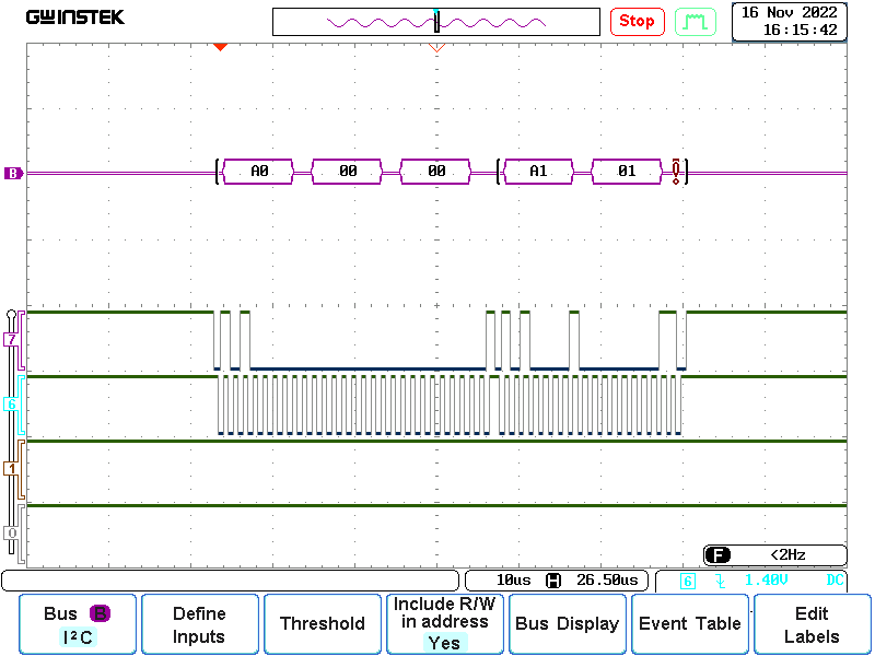
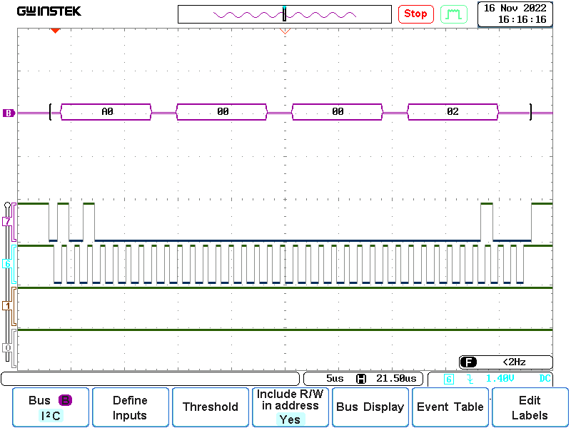
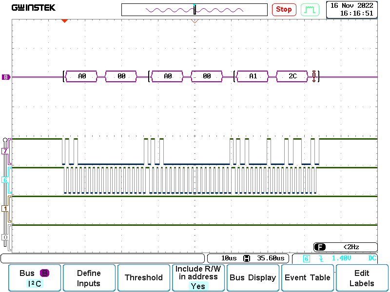
I2C: 16bit EEPROM adresses are split on the SECOND read
Hi Jeremy,
I spent some time investigating my code and could not find the problem.
Then I came back to your code and adjusted it a little bit to enable me to debug it better.
I do appreciate, that you do not have time to resolve this soon, I just wanted to make sure that I used your code (not mine) to reproduce it.
Let me know, if I did something wrong.
I have this in my alire.toml:
[[depends-on]]
pico_bsp = "^2.0.0"
See code below:
with RP.Device;
with RP.Clock;
with RP.GPIO;
with RP.I2C_Master;
with Pico;
with HAL.I2C;
with HAL; use HAL;

procedure Jeremy is
   use RP.GPIO;
   use HAL.I2C;

   SCL  : GPIO_Point renames Pico.GP15;
   SDA  : GPIO_Point renames Pico.GP14;
   Port : RP.I2C_Master.I2C_Master_Port renames RP.Device.I2CM_1;
   Addr : constant I2C_Address := 2#1010_000_0#;

   --------------------------------------------------------------------------
   --  HOLGER: make the size of the array adjustable
   ARRAY_SIZE : constant Integer := 1;

   --------------------------------------------------------------------------
   --  HOLGER: add array for Writing
   Data_W     : I2C_Data (1 .. ARRAY_SIZE) := (others => 0);

   --------------------------------------------------------------------------
   --  HOLGER: add array for Reading
   Data_R     : I2C_Data (1 .. ARRAY_SIZE);

   Status     : I2C_Status;
begin
   RP.Clock.Initialize (Pico.XOSC_Frequency);
   RP.Clock.Enable (RP.Clock.PERI);
   Pico.LED.Configure (Output);
   Pico.LED.Set;

   SCL.Configure (Output, Pull_Up, RP.GPIO.I2C, Schmitt => True);
   SDA.Configure (Output, Pull_Up, RP.GPIO.I2C, Schmitt => True);
   Port.Configure (Baudrate => 400_000);

   RP.Device.Timer.Enable;

   --------------------------------------------------------------------------
   --  HOLGER: complete loop unrolling to focus on the problem
   --          and make debugging easier

   --------------------------------------------------------------------------
   --  HOLGER: Case Data_W (1) := 1
   Data_W := (others => Data_W (1) + 1);
   Port.Mem_Write
     (Addr          => Addr,
      Mem_Addr      => 0,
      Mem_Addr_Size => Memory_Size_16b,
      Data          => Data_W,
      Status        => Status,
      Timeout       => 1000);
   if Status = Ok then
      Pico.LED.Set;
   end if;
   RP.Device.Timer.Delay_Milliseconds (500);

   Port.Mem_Read
     (Addr          => Addr,
      Mem_Addr      => 0,
      Mem_Addr_Size => Memory_Size_16b,
      Data          => Data_R,
      Status        => Status,
      Timeout       => 1000);
   if Status = Ok then
      Pico.LED.Set;
   end if;
   RP.Device.Timer.Delay_Milliseconds (500);

   --------------------------------------------------------------------------
   --  HOLGER: compare the array written with the array read
   for I in 1 .. ARRAY_SIZE loop
      if Data_W (I) /= Data_R (I) then
         --------------------------------------------------------------------
         --  Holger: STOP if data different: it is the same
         Pico.LED.Clear;
         loop
            null;
         end loop;
      end if;
   end loop;

   --------------------------------------------------------------------------
   --  HOLGER: Case Data_W (1) := 2
   Data_W := (others => Data_W (1) + 1);
   Port.Mem_Write
     (Addr          => Addr,
      Mem_Addr      => 0,
      Mem_Addr_Size => Memory_Size_16b,
      Data          => Data_W,
      Status        => Status,
      Timeout       => 1000);
   if Status = Ok then
      Pico.LED.Set;
   end if;
   RP.Device.Timer.Delay_Milliseconds (500);

   Port.Mem_Read
     (Addr          => Addr,
      Mem_Addr      => 0,
      Mem_Addr_Size => Memory_Size_16b,
      Data          => Data_R,
      Status        => Status,
      Timeout       => 1000);
   if Status = Ok then
      Pico.LED.Set;
   end if;
   RP.Device.Timer.Delay_Milliseconds (500);

   --------------------------------------------------------------------------
   --  HOLGER: compare the array written with the array read
   for I in 1 .. ARRAY_SIZE loop
      if Data_W (I) /= Data_R (I) then
         --------------------------------------------------------------------
         --  Holger: STOP if data different -> it *is* different!
         Pico.LED.Clear;
         loop
            null;
         end loop;
      end if;
   end loop;

   --------------------------------------------------------------------------
   --  HOLGER: we end here if everything is OK
   loop
      Pico.LED.Set;
   end loop;

end Jeremy;
I used GDB to step through the program, but the same behaviour is true if run as normal without debugger attached.
Those are the results:
Write Data=1 -> OK
Read Data=1 -> OK
Write Data=2 -> OK
Read Data=2 -> NOK
From the RP2040 datasheet:
2.1.2. Atomic Register Access
Each peripheral register block is allocated 4kB of address space, with registers accessed using one of 4 methods,
selected by address decode.
• Addr + 0x0000 : normal read write access
• Addr + 0x1000 : atomic XOR on write
• Addr + 0x2000 : atomic bitmask set on write
• Addr + 0x3000 : atomic bitmask clear on write
Currently, rp2040_hal only uses the normal read write access alias. It might make sense to use the atomic aliases for some operations, but these should be used sparingly. I'd really prefer that concurrent access be mediated by Ravenscar's protected types or the SIO's semaphores.
This needs more investigation to determine the tradeoffs.
There’s a hardware integer divider in the SIO block that would significantly improve the performance of many programs. The assembly code used to hook this up to gcc’s EABI in pico-sdk is intimidating and more complicated than you’d expect.
The boot ROM supports flashing using files in UF2 format. Upstream pico-sdk contains a small C program that converts an ELF file to UF2. It would be nice to have this available in Alire so that users don't have to download and build pico-sdk just to flash a board. Maybe there's a clever way to build this utility as a dependency and call it during alr build.
Hi @JeremyGrosser,
There is a small issue in the call to the flash_range_program ROM procedure here:
      RP.ROM.flash_range_program (Addr  => To_Address (Offset),
                                  Data  => Source,
                                  Count => Interfaces.C.size_t (Length));
The flash offset parameter (Offset) is converted to a System.Address with To_Address which gives an address in the RP2040 memory space, i.e. Offset + XIP_Base . But flash_range_program is expecting an offset in the flash address space.
On the RP.ROM side, I think the type of the Addr parameter is confusing. System.Address is suggesting an address in the RP2040 memory space:
   procedure flash_range_program
      (Addr       : System.Address;
       Data       : System.Address;
       Count      : Interfaces.C.size_t)
flash_range_erase on the other hand has a Unsigned_32 type for Addr which is less error prone I would say:
   procedure flash_range_erase
      (Addr       : Unsigned_32;
       Count      : Interfaces.C.size_t;
       Block_Size : Unsigned_32;
       Block_Cmd  : Unsigned_8)
I see two ways to fix this:
To_Address (Offset) conversion in RP.Flash.ProgramRP.ROM flash_range_erase signature to change the type of AddrWhen rp2040_hal is used with a ZFP runtime, there is no support for using the second CPU core. We should add a wrapper around the SEV instruction and ensure that the startup code will work if executed by both cores. We should still push users toward Ravenscar's tasks and protected types for SMP applications and the documentation should point out the caveats of accessing hardware peripherals from two cores at the same time.
Generating VGA is just a cool demo to have, and may be useful for applications that need a large display. It's one of the more complex PIO programs, so the driver is non-trivial.
Need to verify that the RP.Watchdog driver works as expected. An example should be added to pico_examples.
Recent changes to pico-sdk look like the watchdog timeout was being calculated incorrectly.
fsin, fcos, ftan, etc... only accept arguments in the range -128.0 .. 128.0, we need to write wrappers that either do an entirely soft math operation or scale the argument to fit the range and accept the loss of precision.
From @Fabien-Chouteau on Gitter:
with RP.Timer; use RP.Timer;
with RP.GPIO;

with RP.Clock;

procedure Test_Rp2040_Clocks is
   Next_Start : Time := Clock + Milliseconds (10);
   GP1 : RP.GPIO.GPIO_Point := (Pin => 1);
   GP2 : RP.GPIO.GPIO_Point := (Pin => 2);
begin

   RP.Clock.Initialize;

   GP1.Configure (RP.GPIO.Output);
   GP1.Clear;
   GP2.Configure (RP.GPIO.Output);
   GP2.Clear;
   loop
      GP2.Toggle;
      if Clock >= Next_Start then
         Next_Start := Next_Start + Milliseconds (1);

         GP1.Toggle;
      end if;
   end loop;
end Test_Rp2040_Clocks;
https://gitter.ems.host/_matrix/media/r0/download/matrix.org/qVpFqAJFmfyGpzYmbkwwBwLj
https://gitter.ems.host/_matrix/media/r0/download/matrix.org/NXMJALdTPfSFXkmDxOPFWAlc
https://gitter.ems.host/_matrix/media/r0/download/matrix.org/CwAvXDWeeeLxrmkcnkZwEPEx
In addition to the READMEs, example code, blog posts, and videos, a documentation site should exist.
Make it nice, like the Python standard library docs. Ideally this would be autogenerated, which means we need something akin to docstrings in comments or a way to associate external documentation comments with procedure and function signatures. There are probably existing tools for this.
Reported by @hgrodriguez on gitter:
When calling Mem_Read with Memory_Size_16b, the two address bytes are written in separate transactions, rather than using repeated start.
The pico-extras repository contains an example for accessing an SD card using four data lines. The driver should implement the HAL.SDMMC interface. The Pimoroni Pico VGA board has a microSD card slot wired for this already, so that should be the target of any example code.
We should find a way to handle different ROM versions. The V2 and V3 ROMs contain functions that are not present in V1. If we setup __aeabi symbols for those new functions, we lose the gcc soft math implementations, so the binary is then not compatible with V1 chips. We need to find a way to either link in a soft math implementation as a fallback or provide a compile-time minimum ROM version.
As far as I can tell, the majority of RP2040 chips in the wild have the V2 or V3 ROMs, I believe the V1s were sent to vendors like Adafruit and Arduino prior to public RP2040 availability and some of those early chips got placed on boards shipped to customers. So V1 is rare, but not that rare.
Line 305 in rp-master.adb reads:
A : constant I2C_Data (1 .. 1) := (1 => UInt8 (Mem_Addr));
This raises CE if Mem_Addr > 255.
It should be written as
A : constant I2C_Data (1 .. 1) := (1 => UInt8 (16#FF# and Mem_Addr));
A call to reset_to_usb_boot somehow locks up the device, but it will not properly reboot and show up on USB. Maybe some preparation is required, but looking at the pico-sdk I could not find anything special.
rp2040_hal/src/drivers/rp-rom.ads
Line 154 in 02c3d00
@JeremyGrosser when will v2.1.1 be available on alire?
The usb_embedded library needs to be extended to support this and define a host controller interface.
We should have a driver for reading/writing the external flash via the HAL.Block_Drivers.Block_Driver interface.
There are several problems with the current GPIO interrupt code:
access procedure, one for each pin on every interrupt. This is quite slow.RP.GPIO.Interrupts), making the use of this code optional.When testing the example code in pico_examples for I2C using a BMP280 the low level implementation of the I2C driver works but the abstracted HAL driver does not. It seems to get stuck on Read_Ready when in read stage of the read and subsequently time out.
This was tested with a pair of BMP280s and a Pi Pico.
Also tested with a BMP384 on custom rp2040 board which produces the same result.
Hi @JeremyGrosser,
I merged and removed the critical_sections branch of the atomic repo, so the the pin in alire.toml is broken:
Line 21 in 017bd3f
It returns the same value on two pico boards.
RP.Clock needs to be extended to support changing the clock sources and PLLs dynamically. Example code should demonstrate overclocking to 250 MHz.
Hi @JeremyGrosser,
I got an issue with the default XOSC_Startup_Delay on a Pico board.
My firmware locked in the RP.Clock.Initialize but only on a "cold" start, so I looked a the startup delay.
Looking at the pico-sdk the startup delay is computed this way:
#define STARTUP_DELAY (((((XOSC_MHZ * MHZ) / 1000) + 128) / 256) * PICO_XOSC_STARTUP_DELAY_MULTIPLIER)For 12Mhz, the formula gives:
((XOSC_MHZ * MHZ) / 1000) + 128) = ((12000000 / 1000) + 128) = 12128
which is close to the default in rp2040_hal which is 12_032.
rp2040_hal/src/drivers/rp-clock.ads
Line 21 in 6115fd1
However there is this PICO_XOSC_STARTUP_DELAY_MULTIPLIER value that is set to 64 for different boards (all the Adafruit ones and the seeed xiao). I changed the XOSC_Startup_Delay to 12_032 * 64 and now the board boots flawlessly.
So I don't know what's going on with this specific Raspberry Pi Pico. Maybe out of spec crystal or capacitors. Maybe my carrier board is having an effect...
I have a way to fix the issue on my side, but I wonder if we should use a "safer" default for the XOSC_Startup_Delay value.
Hi Jeremy,
first of all thanks a lot for your great work to implement this software which is so useful.
I was looking at your example: spi_loopback and I found the Test_Slave procedure perfectly working.
As this is implemented as 16b, I tried to implement an 8b version as an exercise for me.
(I do not have your debug setup yet, so I am stuck with a logic analyzer)
Using my logic analyzer I can confirm, that your code using 16b works. Changing this to 8b seems not working.
The code below is the bare minimum code I can offer to re-produce.
I kept all your output/pragma as comments, as I do not have the setup yet.
Again thanks for all your work.
I hope the code below (it compiles at my side without any problems) helps to identify the issue.
Regards,
Holger
PS: I tried to insert the code below as code, but somehow I do not get it. Sorry for this, you may have to reformat on your side :-(
============================================
with HAL;
with HAL.SPI;
with RP.Clock;
with RP.GPIO;
with RP.SPI;
with RP.Device;
with Pico;
with Board;
procedure Main_TestSlave_16_8 is
procedure Test_Slave_16
(Name : String;
Master_Config : RP.SPI.SPI_Configuration;
Slave_Config : RP.SPI.SPI_Configuration)
is
-- Things need to happen in the following order:
-- 1. Set A := I, B := not I
-- 2. Put A in the slave's transmit FIFO
-- 3. Transmit B from the master to generate a clock
-- 4. Read A from the master FIFO into B, check A = B
-- 5. Read B from the slave FIFO into A, check A = not B
A : HAL.SPI.SPI_Data_16b (1 .. 1) := (others => 0);
B : HAL.SPI.SPI_Data_16b (1 .. 1) := (others => 0);
Status : HAL.SPI.SPI_Status;
use HAL;
begin
-- Ada.Text_IO.Put (Name & "...");
Board.SPI_Master.Configure (Master_Config);
Board.SPI_Slave.Configure (Slave_Config);
  --  Slave to master
  for I in 1 .. 1 loop
     A (1) := HAL.UInt16 (16#5A5A#);
     B (1) := not A (1);

     Board.SPI_Slave.Transmit (A, Status);
     --  pragma Assert (Status = Ok, "Slave transmit: " & Status'Image);

     Board.SPI_Master.Transmit (B, Status);
     --  pragma Assert (Status = Ok, "Master transmit: " & Status'Image);

     Board.SPI_Master.Receive (B, Status);
     --  pragma Assert (Status = Ok, "Master receive: " & Status'Image);
     --  pragma Assert (A = B, "Master received incorrect value: " &
     --                   "A = " & A (1)'Image & ", " &
     --                   "B = " & B (1)'Image);

     Board.SPI_Slave.Receive (A, Status);
     --  pragma Assert (Status = Ok, "Slave receive: " & Status'Image);
     --  pragma Assert (A (1) = not B (1));
  end loop;
  --      Ada.Text_IO.Put_Line ("PASS");
end Test_Slave_16;
procedure Test_Slave_8
(Name : String;
Master_Config : RP.SPI.SPI_Configuration;
Slave_Config : RP.SPI.SPI_Configuration)
is
-- Things need to happen in the following order:
-- 1. Set A := I, B := not I
-- 2. Put A in the slave's transmit FIFO
-- 3. Transmit B from the master to generate a clock
-- 4. Read A from the master FIFO into B, check A = B
-- 5. Read B from the slave FIFO into A, check A = not B
A : HAL.SPI.SPI_Data_8b (1 .. 1) := (others => 0);
B : HAL.SPI.SPI_Data_8b (1 .. 1) := (others => 0);
Status : HAL.SPI.SPI_Status;
use HAL;
begin
-- Ada.Text_IO.Put (Name & "...");
Board.SPI_Master.Configure (Master_Config);
Board.SPI_Slave.Configure (Slave_Config);
  --  Slave to master
  for I in 1 .. 1 loop
     A (1) := HAL.UInt8 (16#5A#);
     B (1) := not A (1);

     Board.SPI_Slave.Transmit (A, Status);
     --  pragma Assert (Status = Ok, "Slave transmit: " & Status'Image);

     Board.SPI_Master.Transmit (B, Status);
     --  pragma Assert (Status = Ok, "Master transmit: " & Status'Image);

     Board.SPI_Master.Receive (B, Status);
     --  pragma Assert (Status = Ok, "Master receive: " & Status'Image);
     --  pragma Assert (A = B, "Master received incorrect value: " &
     --                   "A = " & A (1)'Image & ", " &
     --                   "B = " & B (1)'Image);

     Board.SPI_Slave.Receive (A, Status);
     --  pragma Assert (Status = Ok, "Slave receive: " & Status'Image);
     --  pragma Assert (A (1) = not B (1));
  end loop;
  --  Ada.Text_IO.Put_Line ("PASS");
end Test_Slave_8;
begin
RP.Clock.Initialize (Pico.XOSC_Frequency);
RP.Device.Timer.Enable;
Pico.LED.Configure (RP.GPIO.Output);
Board.Initialize;
loop
if True then
Test_Slave_16 ("Slave transmit 16b",
Master_Config =>
(Role => RP.SPI.Master,
Baud => 10_000_000,
Data_Size => HAL.SPI.Data_Size_16b,
others => <>),
Slave_Config =>
(Role => RP.SPI.Slave,
Baud => 10_000_000,
Data_Size => HAL.SPI.Data_Size_16b,
others => <>));
else
Test_Slave_8 ("Slave transmit 8b",
Master_Config =>
(Role => RP.SPI.Master,
Baud => 10_000_000,
Data_Size => HAL.SPI.Data_Size_8b,
others => <>),
Slave_Config =>
(Role => RP.SPI.Slave,
Baud => 10_000_000,
Data_Size => HAL.SPI.Data_Size_8b,
others => <>));
end if;
Pico.LED.Toggle;
end loop;
end Main_TestSlave_16_8;
See conversation on Gitter for details.
While the RP2040 will never be a high reliability chip, it would be nice to make some assertions about the quality of the driver code. At the moment, gnatprove bails out somewhere in usb_embedded due to some pointer/class dispatch ambiguity.
svd2ada will also need to be modified to add Effective_Reads and Async_Writers to most of the register definitions.
I don't view SPARK verification as a critical project, there are certain operations in rp2040_hal that will always be somewhat unsafe, like DMA transfers and checking clock frequencies- these cannot be statically verified without modeling the entire clock tree.
A declarative, efficient, and flexible JavaScript library for building user interfaces.
🖖 Vue.js is a progressive, incrementally-adoptable JavaScript framework for building UI on the web.
TypeScript is a superset of JavaScript that compiles to clean JavaScript output.
An Open Source Machine Learning Framework for Everyone
The Web framework for perfectionists with deadlines.
A PHP framework for web artisans
Bring data to life with SVG, Canvas and HTML. 📊📈🎉
JavaScript (JS) is a lightweight interpreted programming language with first-class functions.
Some thing interesting about web. New door for the world.
A server is a program made to process requests and deliver data to clients.
Machine learning is a way of modeling and interpreting data that allows a piece of software to respond intelligently.
Some thing interesting about visualization, use data art
Some thing interesting about game, make everyone happy.
We are working to build community through open source technology. NB: members must have two-factor auth.
Open source projects and samples from Microsoft.
Google ❤️ Open Source for everyone.
Alibaba Open Source for everyone
Data-Driven Documents codes.
China tencent open source team.