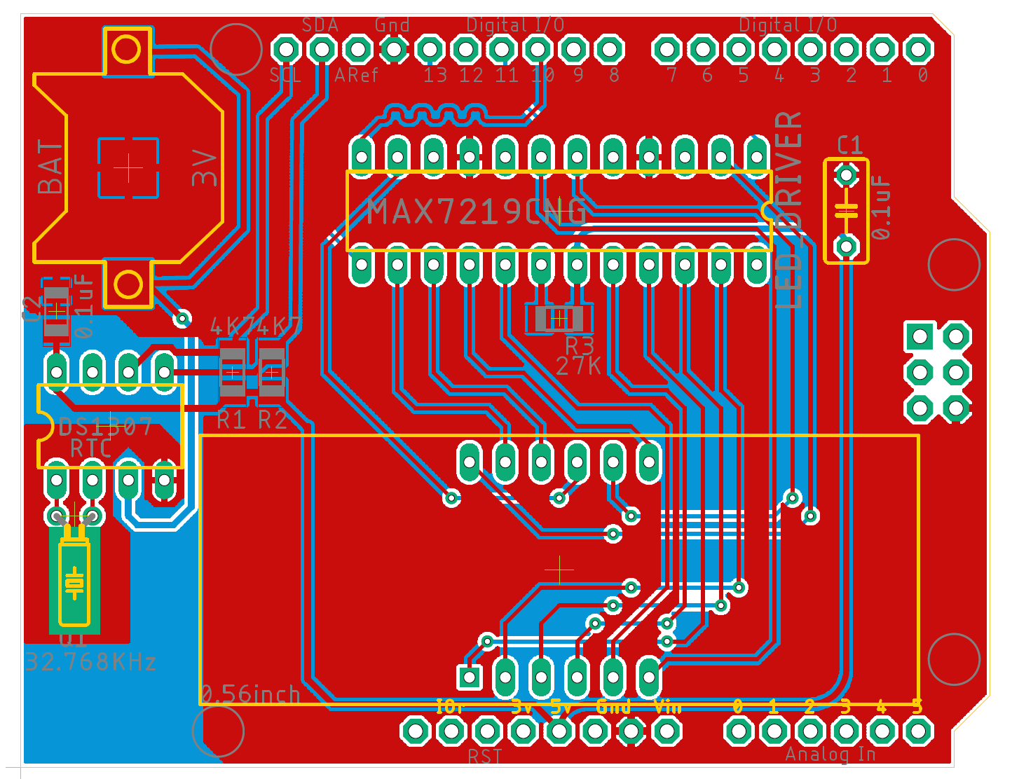
Designed an LED Display PCB using Arduino UNO (R3) on Autodesk EAGLE. This was the final project of a course I'm pursuing on Udemy and successfully created the PCB without any errors. I learnt a lot about design rules and design issues that arise while designing any PCB and, for that matter, this design taught me how to tackle those issues related to EMI (Electromagnetic Interference) and how to achieve high-frequency and high-speed circuits with minimal noise production.
- 7 Segment (4 Digit LED Display)
- Real Time Clock (RTC)- 32.768 KHz Crystal (I2C Communication with Arduino)
- LED Display Driver Module- MAX7219CNG (SPI Communication with Arduino)
- SMD Resistors & Capacitors as well as THT Capacitor
- Back-up Battery Port to maintain a clock if the PCB is turned-off.
This PCB is capable of displaying any data (such as clock, date, stop watch, sensor outputs, etc.) depending on your project requirements.
The LED Driver module utilises SPI communication protocol with the Arduino and hence you can see an SPI BUS (Blue colour in schematic).
The RTC utilises I2C communication protocol with the Arduino as mentioned in its data-sheet for the DS1307 Integrated Chip.


Here, we can see that the BOLD BLUE line in across the schematic is the SPI BUS interface needed for the communication between the LED Driver/LED Display and the Arduino. While the RTC uses I2C communication protocol to interface with the Arduino.
