- For the initial setup, construction and only configuring the
WiFiof the printer and enclosure, please follow this guide - For the original manual of the CR6-SE, please refer to this PDF
- For all of the slicer configs and profiles please refer to the Slicer Profiles section.
This is my implementation for my 3D printing enclosure. The enclosure runs the following software:
- Klipper: The
firmwarefor the printer. Klipper is installed on both the printer and theRaspberry Pi - Mainsail: The front-end for
Klipper, which allows for a simple interface with the printer. You can find the official documentation here - Moonraker: An API server used by both
KlipperandMainsailto communicate with each other. You can find the official documentation here - ESP Home: The
firmwarefor theESP32which controls the enclosure heating and lights. You can find the official documentation here - Mosquito: A
MQTT Brokerused to implement communication between theESP32, printer andRaspberry Pi. Here you can find easy installation instructions but it will be explained in the following sections.
This section is only relevant if the user wishes to do a complete fresh installation of the entire system. If you wish to only configure the WiFi settings, please refer to this guide.
This could be necessary if they user bricked the system in some way, which is not easily possible, they wish to reproduce the original system or wish to replicate it and create a new system. It is advised that a user reads the entire installation process for better understanding. This process might appear intimidating, but is actually quite simple and can easily be completed in about an hour of simply typing Linux terminal commands.
An important thing to note is, when completing a fresh install, the Raspberry Pi will have no network connection initially. Thus, it is required to connect the Raspberry Pi to an external monitor with a keyboard and a wireless dongle. The fresh operating system MainsailOS will then be installed and the initial setup will be completed. Once the network configuration has been completed, the user can disconnect the Raspberry Pi from the external monitor and use SSH for further configuration.
Only completed the following section if you are running a fresh install. Otherwise skip directly to the network configuration if you wish to connect the system to a new network and the software has already been installed.
In this section we will be installing MainsailOS. MainsailOS is a Linux based operating system, which is pre-configured to run Klipper, Mainsail and Moonraker. This simplifies the installation process and the user is only required to flash a new operating system to the Raspberry Pi for the installation of Klipper.
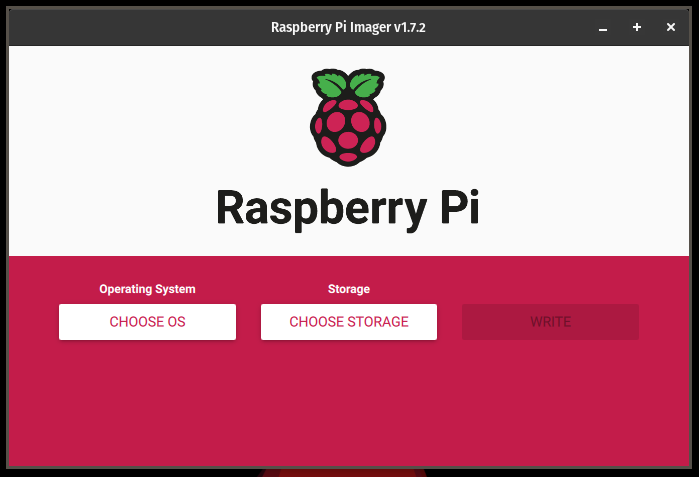
We will start by downloading and installing rpi-imager on a secondary computer to create an operating system image for the Raspberry Pi SD card. You can easily download it from here or use the following command on a Linux system
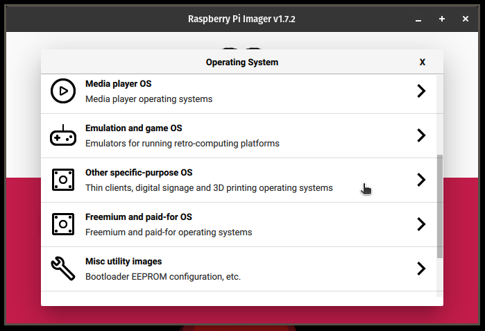
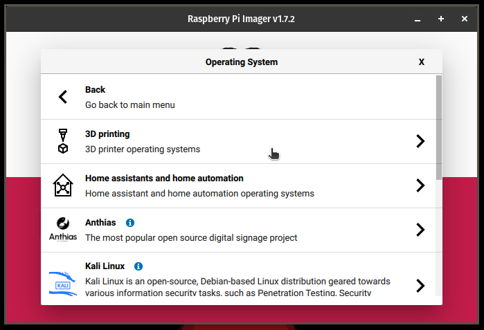
sudo apt install rpi-imager- Open
rpi-imagerand clickOther specific-purpose OS > 3D Printing > Mainsail OSand choose the32-bitversion. - Insert the
SD cardof theRaspberry Piinto the computer and select it as the storage device forrpi-imager. - Click the
gear-iconin the bottom right corner ofrpi-imager - Set
hostnameasmainsail.local. - Enable
SSHwithUse password authentication, defaultusername = piandpassword = root - Skip
Configure Wireless LANas this does not always work and will be configured in the next step in order to be more reliable and work correctly - Click
Save - Click
Write. If prompted to format theSD cardclickyes. - Wait for the installation to complete. This might take a few minutes depending on internet speed and the write speed of the
SD card

Remove the SD card from the computer and insert it into the Raspberry Pi. Connect the Raspberry Pi to an HDMI monitor and a keyboard and finally connect the power. Wait for the Raspberry Pi to boot. Ensure that your WiFi dongle is plugged into the Raspberry Pi.
==This should be completed for the initial setup in order to connect the Raspberry Pi to your network as well as after an initial fresh install of Klipper and MainsailOS as explained in the previous section==
On the first boot, the screen may flash a test image, simulating a rainbow pattern and present a scrolling terminal of text showing checks and other information. Wait for the this screen to stop scrolling and wait for a prompt asking for your username:
raspberrypi login: Enter pi. A next prompt asking for your password will be shown. Important, while typing in your password, no text will be shown in the terminal. Enter root:
Password: Next we need to configure the Raspberry Pi. Run the following command in the terminal. You may be prompted for your password, enter the password as configured previously or the default password root
sudo raspi-configUse the arrow keys to select 1 System Options, select S1 Wireless LAN enter the SSID of your WiFi network. The SSID is the name of your network, such as the name shown on a phone or computer when connecting to the network. Be sure to enter it perfectly as it is case-sensitive.
After entering your SSID press enter and you will be prompted for your password. This is the password for your WiFi network. Press enter once complete.
You'll be returned to the home screen. Select 1 System Options again and select Hostname. Enter your own desired unique hostname. For this guide the hostname mainsail was chosen. Press enter once complete.
On the home screen again, select 3 Interface Options and select I2 SSH, follow the guide to enable SSH. Repeat this for the same menu 3 Interface Options to enable I4 SPI, I5 I2C, I6 Serial Port, I7 1-Wire and I8 Remote GPIO.
SSHallows you to login to yourRaspberry Piover a remote terminal connectionSPI,I2Cand1-Wireare all communication protocols which can be used to communicate with external sensors and modules. Not all of them are necessarily used with the current implementation, but enabling them might allow for easier setup in the future.Serial Portallows for serial communication over USBRemote GPIOallows for controlling theGPIOpins remotely. This is often used by someAndroidapps and other applications and enabling it now would also simplify future configurations.
Back on the home screen of raspi-config, press the right-arrow key to move the cursor to the Finish button in the bottom right corner. Press enter. If prompted to reboot, select yes and press enter. The Raspberry Pi will restart. Wait for this to finish and login with your username and password again once the reboot has been completed.
Although the WiFi settings have been enabled and you provided your SSID and password in the previous section, this does not always work, depending on your Wifi dongle and network. Thus the following configuration should be completed:
Enter the following commands line by line separately in the terminal, pressing enter after every line. Be sure to replace ssid with your WiFi network name and password with your password. They should be enclosed by the single quotes.
sudo rfkill unblock wifi
sudo sh -c "wpa_passphrase 'ssid' 'password' >> /etc/wpa_supplicant/wpa_supplicant.conf"
sudo wpa_cli -i wlan0 reconfigure
Reboot the Raspberry Pi again by typing reboot into the terminal. Wait for the Raspberry Pi to reboot and login again.
Once the system is booted, enter the command ifconfig and you'll be presented by an output such as the following:
pi@mainsail:~ $ ifconfig
eth0: flags=4099<UP,BROADCAST,MULTICAST>  mtu 1500
        ether b8:27:eb:3c:98:b5  txqueuelen 1000  (Ethernet)
        RX packets 0  bytes 0 (0.0 B)
        RX errors 0  dropped 0  overruns 0  frame 0
        TX packets 0  bytes 0 (0.0 B)
        TX errors 0  dropped 0 overruns 0  carrier 0  collisions 0

lo: flags=73<UP,LOOPBACK,RUNNING>  mtu 65536
        inet 127.0.0.1  netmask 255.0.0.0
        inet6 ::1  prefixlen 128  scopeid 0x10<host>
        loop  txqueuelen 1000  (Local Loopback)
        RX packets 12  bytes 1698 (1.6 KiB)
        RX errors 0  dropped 0  overruns 0  frame 0
        TX packets 12  bytes 1698 (1.6 KiB)
        TX errors 0  dropped 0 overruns 0  carrier 0  collisions 0

wlan0: flags=4163<UP,BROADCAST,RUNNING,MULTICAST>  mtu 1500
        inet 192.168.1.59  netmask 255.255.255.0  broadcast 192.168.1.255
        inet6 fe80::b087:ae52:2982:2133  prefixlen 64  scopeid 0x20<link>
        ether c8:3a:35:c3:d9:3e  txqueuelen 1000  (Ethernet)
        RX packets 655  bytes 145261 (141.8 KiB)
        RX errors 0  dropped 0  overruns 0  frame 0
        TX packets 344  bytes 156595 (152.9 KiB)
        TX errors 0  dropped 0 overruns 0  carrier 0  collisions 0
Note the output for wlan0, this is the Wireless dongle. The section inet 192.168.1.59 is the ip address of the Raspberry Pi on your network. ether c8:3a:35:c3:d9:3e is the MAC address of the dongle. The ip address in your output may differ as this is provided by your network and router. The MAC address might be the same depending on the dongle you used.
The ip address displayed in the previous section is very important. This is the address of the printer on the network. Although the ip address is supplied by your router, it might not remain constant and may change every 48 hours or so, which is not desired. For this reason, we want to supply it with a static ip address, this will ensure that the Raspberry Pi will always have the same address, which is required for you to easily connect to your printer as well as connect the ESP32 which controls the enclosure to your printer.
First, we need to find the ip address of your router. Run the following command to get this:
ip r | grep defaultThe output should look something like this:
default via 192.168.1.1 dev wlan0 proto dhcp src 192.168.1.59 metric 303 Note the part 192.168.1.1, which might differ for you, this is the ip address of your router. We will call it <router ip> for now, that you can use it in the following sections.
Next, we need to find your DNS server. You can find this using the following command. This command will prompt you for your password of your Raspberry Pi and open the terminal text editor afterwards.
sudo nano /etc/resolv.confThe output should look something like this:
# Generated by resolvconf
domain RT-AC58U_V3-3C28
nameserver 192.168.1.1
Note the ip address after nameserver. We will call this <dns ip>. Press ctrl+x to exit this editor and return to the terminal.
Now we are ready to set the static ip address. Start by entering the following command. This will once again open a terminal text-editor.
sudo nano /etc/dhcpcd.confThe output in your terminal will then possibly be an empty text file or the might be some other configurations. If settings already exist, update the information, other simply enter the following:
NETWORKshould be replaced with your interface that you are using, in the case of aWiFi dongleyou need to enterwlan0STATIC_IP/24should be replaced with your desiredip address. For this guide we will use192.168.1.59/24. If you choose your ownip address, be sure that the third digit marked by an x192.168.x.yneeds to be the same as the third digit in your<router ip>we found earlier and y should always be less than255and never numbers like0,1,10,99or100as they are often used by your network or router, but your could use them if you know what you are doing.ROUTER_IPshould be replaced by your<router ip>we found in the previous section.DNS_IPshould be replaced by your<dns ip>found in the previous section
interface NETWORK
static ip_address=STATIC_IP/24
static routers=ROUTER_IP
static domain_name_servers=DNS_IP
Thus, my implementation looked something like this. Important, if your file contains a lot of other information, do not change any of these settings. Also, if the lines already exist in the file, but they start with a #, remove it. The # acts as a comment line and these lines are thus commented out and not active, as seen below in my configuration.
interface wlan0
static ip_address=192.168.1.59/24
static routers=192.168.1.1
static domain_name_servers=192.168.1.1 8.8.8.8 fd51:42f8:caae:d92e::1
Once done, press ctrl+x and you will be prompted at the bottom of the screen to save the file. Press shift+y to select yes and press enter to confirm to overwrite the file contents. You will then be returned to the terminal screen. Finally, we can reboot the system again, by running the command reboot in the terminal.
You have now completed the initial setup of the Raspberry Pi. We installed MainsailOS which includes Klipper and Mainsail which we will use to control the printer. We also connected the Raspberry Pi to the network and configured a static ip address which will ensure that we can easily connect to it over the network. Next we need to install Klipper on the printer itself.
Klipper is an open-source firmware which off-sets the computation from the printer to a Raspberry Pi. This allows the Raspberry Pi to handle all of the heavy computation and only communicates the required kinematics with the printer. This allows for faster printing as well as other advanced features such as input shaping, pressure advance and the connection of other external processors and modules.
This process involves two installation. The installation of Klipper on the Raspberry Pi and on the printer itself. The installation on the Raspberry Pi has already been completed in the previous sections and only the printer is remaining.
Please refer to the official documentation but the following guide can also be followed. Also, this step can be skipped and the default firmware.bin file can be found in the firmware/ folder of this repository, copy this file to your SD card and skip to the end of this section to flash the file to your printer.
First start by setting up the Raspberry Pi. You can connect the Raspberry Pi to an HDMI monitor and use a keyboard as in the previous sections or you can connect to the Raspberry Pi using SSH. This can be achieved using a dedicated SSH terminal or using the following command in either Windows, Linux or Mac terminals. Where pi is replaced with the username you previously chose and 192.168.1.59 with the static ip you chose in the previous steps. Press enter and follow the on screen instructions. The terminal will then connect to the Raspberry Pi and grant you access to the terminal similar to the terminal you used when the Raspberry Pi was directly connected to your monitor. If you aren't using an SSH connection, skip the following command and continue directly to the next command where we move to the directory of Klipper in the terminal of the Raspberry Pi:
Once connected to the terminal, enter the following command to move to the directory of Klipper on the Raspberry Pi:
cd klipper/Once in this directory, we want to create the firmware file you'll be flashing to the printer. First start by entering the following command:
make menuconfig
You will then be presented with a menu similar to the the menu you used when we usec raspi-config in the previous steps. Use the arrow keys to move down to the second option Micro-controller Architecture (...) where ... might be some arbitrary text depending on the last setup used, and press enter.
Once again use the arrow keys to move down and select STMicroelectornics STM32 and press enter. Select processor model "STM32F103" (is the default), set Bootloader offset to Bootloader - "28KiB" and Communication interface to Serial (on USART1 PA10/PA9). If you get stuck, a great guide can be found here. Otherwise, there is also this guide on Reddit.

Press shift+q and press shift+y to save the settings. This will save the config which we want to use for building our firmware. Once back in the terminal, enter the following command to build the firmware for your printer. This might take a few minutes and the terminal may scroll automatically with a lot of logs and information regarding the build:
makeIf this is successful, you'll se the file klipper.bin in the directory if you enter ls out/ to list the files in the out/ directory. This is the file we are interested in. If you have changed anything in the afore mentioned config, you need to copy this file to an SD Card, otherwise this file has already be provided in the firmware folder of this repository and you can simply copy it to an SD card and rename it to firmware.bin. Please note, that this klipper.bin file was generated on 2023-10-19 and might be out of date at the time of your usage.
Copy this firmware.bin file to your SD card. Be sure to turn your printer off. Insert the SD card and power-on the printer. Wait for the about 60 seconds for the printer to automatically install the firmware. Be sure that the printer is off before inserting the SD card and is turned on while it is already inserted. The printer checks for this file on the SD card at startup.
Important. For some reason, this step isn't always successful. In my personal experience it always takes about 2 or 3 tries. So I insert the SD card, power-on the printer, wait 60 seconds and then power the printer off. I then repeat this process 2 or 3 times to be sure that it flashes. This is simply due the printer's nature and is a well known "bug" with this process. If you find that the Raspberry Pi cannot connect to the printer in the following sections or that it does not detect it, it might be due to this step failing.
If you are unable to flash the firmware, please confirm that the correct settings were chosen in the previous section.
Due to certain dependencies, their is a third and final Klipper installation which needs to be completed for this implementation to work correctly. This involves installing some low-level firmware of Klipper to allow the Linux operating system on the Raspberry Pi to communicate with some of the hardware on the Raspberry Pi. This is however quite easy and can be completed with the following commands, the official documentation for this process can also be found here.
cd ~/klipper/
sudo cp ./scripts/klipper-mcu.service /etc/systemd/system/
sudo systemctl enable klipper-mcu.service
Then we need to compile the firmware for the for the Raspberry Pi, similar to the firmware we compiled for the printer:
cd ~/klipper/
make menuconfig
In the menu, set Microcontroller Architecture to Linux process then save and exit. Finally, we can flash it to the Raspberry Pi:

sudo service klipper stop
make flash
sudo service klipper startKlipper functions a bit differently to the standard Marlin firmware shipped with most printers. Rather than having the configuration of the printer be fixed at compile time of the firmware, you can change it at anytime. Thus, you can change certain features on your printer after flashing the firmware.bin file to your printer. These settings are contained in the printer.cfg file. Please refer to the following page on the Klipper website for more information regarding the configuration file. You can also find the official Creality config file on their Github, which they used for their SonicPad which can be found here.
It is not required to understand everything, but the configuration defines all the parameters, limits and specifications of the printer for Klipper to operate. A perfect starting printer.cfg file for this implementation can be found on the configurations/ directory of this repository. We'll start by copying all of the content in the configurations/ folder in this repository to the printer_data folder on the Raspberry Pi. This will copy the config folder which contains all of the configurations, as well as some example g-code in the gcode folder and finally some other files such as the moonraker.secrets file which contains credentials used by Moonraker to connect to the MQTT server we will install in the following sections.
First start by ensuring that you are in the root directory of the Raspberry Pi, by running the following command
cd ~Then we want to clone this repository to the Raspberry Pi. What this does exactly isn't really important, but you can imagine it to downloading and copy all of the files in this repository to the Raspberry Pi, which make a lot of tasks easier.
While still in the root directory, run the following command to clone this repository. There might be some text output to the terminal during this process:
git clone https://github.com/e-dreyer/OpenEnclosure.gitThe output should look something like this:
pi@mainsail:~ $ git clone https://github.com/e-dreyer/OpenEnclosure.git
Cloning into 'OpenEnclosure'...
remote: Enumerating objects: 89, done.
remote: Counting objects: 100% (89/89), done.
remote: Compressing objects: 100% (64/64), done.
remote: Total 89 (delta 37), reused 72 (delta 24), pack-reused 0
Receiving objects: 100% (89/89), 177.15 KiB | 643.00 KiB/s, done.
Resolving deltas: 100% (37/37), done.
We can then move into this directory with the following command
cd OpenEnclosureUsing the following command, you will be able to see all of the files in this repository now on your Raspberry Pi:
lsNow let's copy some of these files over to the correct Klipper directories to configure your Klipper installation. Let's first navigate back to the root directory to make things easier:
cd ~Now we want to copy all of the config files to the correct Klipper directory. This command copies all of the files in OpenEnclosure/configurations/config to printer_data/config on the Raspberry Pi and the -r flag specifies this operation to be recursive to ensure that all sub folders and files are also copied over:
cp -r OpenEnclosure/configurations/config/* printer_data/config/Finally, we just need to copy over some files which are used to store passwords and other configurations:
cp OpenEnclosure/configurations/moonraker.asvc printer_data/cp OpenEnclosure/configurations/moonraker.secrets printer_data/We are almost done, we only have two more systems to install, then we can start printing!
Next we need to install an MQTT Broker on the Raspberry Pi. MQTT is a communication protocol often used by Internet-of-things or IOT devices and is similar to the http://... or https://... you see before website urls, but specifically made for devices such as printers and the enclosure. A MQTT Broker can be seen as a server and allows other devices to talk to each other over this server. In this case, a MQTT Broker will be hosted on the Raspberry Pi and the ESP32 of the enclosure and the Moonraker API we installed along side Klipper in the first section will talk to each other. This setup is far easier than it sounds and also involves only a few terminal commands.
Here you can find an easy tutorial to install the Mosquitto MQTT Broker, but it will also be explained below. First we need to update the Raspberry Pi. This will allow it to have the latest versions of the software. You can do this by running the following command. While this command is running, you might be prompted to confirm certain software installations by pressing shift+Y to confirm yes. Also, initially you will be prompted for you password as the sudo keyword is used. This is the password of the Raspberry Pi, in this guide we previously defined it as root
sudo apt update && sudo apt upgradeNow we are ready to install Mosquitto, let's start by first running the following command:
sudo apt install -y mosquitto mosquitto-clientsWe also want Mosquitto to auto-start when the Raspberry Pi is powered on. You can enable this by entering the following command:
sudo systemctl enable mosquitto.serviceWe can now test our MQTT Broker by entering the following command. The -v flag is for the verbose mode, which enables logging. The MQTT Broker should start and you should see a log of text and information scrolling on the terminal:
mosquitto -vThis is great, but we need to enable some security to only allow a device to connect to the MQTT Broker with a specific username and password. An important thing to note here is that the MQTT Broker only has a single username and password. Thus, it is configured once and all devices connecting to it should use this specific username and password. You can chose any username and password, but I advise using good security practices with strong passwords for this:
Let's start by creating a new username with the following command, where YOUR_USERNAME is the username you would like to use
sudo mosquitto_passwd -c /etc/mosquitto/passwd YOUR_USERNAMEFor this guide, I will be using username = mainsail and my command looked something like this:
sudo mosquitto_passwd -c /etc/mosquitto/passwd mainsailWhen you run the preceding command with the desired username, you’ll be asked to enter a password. No characters will be displayed while you enter the password. Enter the password and memorize the user/pass combination, you’ll need it later in your projects to make a connection with the MQTT Broker. This previous command creates a password file called passwd on the /etc/mosquitto directory.
Run the following command to edit this file:
sudo nano /etc/mosquitto/mosquitto.confAdd the following line at the top of the file (make sure it is at the top of the file, otherwise it won’t work):
per_listener_settings trueAdd the following three lines to allow connection for authenticated users and tell Mosquitto where the username/password file is located.
allow_anonymous false
listener 1883
password_file /etc/mosquitto/passwd
Your configuration file will look as follows
# Place your local configuration in /etc/mosquitto/conf.d/
#
# A full description of the configuration file is at
# /usr/share/doc/mosquitto/examples/mosquitto.conf.example

per_listener_settings true

pid_file /run/mosquitto/mosquitto.pid

persistence true
persistence_location /var/lib/mosquitto/

log_dest file /var/log/mosquitto/mosquitto.log

include_dir /etc/mosquitto/conf.d
allow_anonymous false
listener 1883
password_file /etc/mosquitto/passwd
Press ctrl+x, then shift+y, and finally press enter to exit and save the changes.
Restart Mosquitto for the changes to take effect.
sudo systemctl restart mosquittoTo check if Mosquitto is actually running, you can run the following command:
sudo systemctl status mosquittoYou can press ctrl+d or ctrl+c to exit this output.
It is now a good time for us to restart the Raspberry Pi to save all of these settings. You can do this by running the command:
rebootFinally, we just need to set this username and password for Moonraker, let's open the moonraker.secrets file to do this. If you are not in the root directory, start by going to the root directory with cd ~ and then open the file with:
nano printer_data/moonraker.secretsYou'll be presented with a file, similar to this following output. Change the username and password to the values you configured for your MQTT Broker:
[mqtt_credentials]
username: mainsail
password: root
To save, we press ctrl+x, ctrl+y and then press enter as we did in the previous sections to exit the nano text editor.
We are now ready for the last section of this installation and then we can start printing!
In this section we will install and configure the ESP32 which is used to control the enclosure. The ESP32 is a small microcontroller with WiFi capabilities. After this section it will be able to connect to the Raspberry Pi over WiFi and receive information regarding its operation and the desired temperature settings. To achieve this, we need to install the ESP Home firmware on the ESP32. This involves a pre-configured config file .yaml file. The user is however only required to make changes to the secrets.yaml file which will set the static ip similar to what we did with the Raspberry Pi in the previous sections, configure the credentials to the network and our MQTT Broker and finally, one or two other required parameters.
The enclosure is controlled by an ESP32 and has the following features:
- A temperature sensor
enclosure_temperature_sensorfor measuring the temperature of the enclosure. - A set of heating lamps
enclosure_heating_lightswhich are used to heat the enclosure. - A configured climate and PID
enclosure_heating_lights_climateto control the brightness ofenclosure_heating_lightsto establish a stable and controlled temperature. The temperature is measured byenclosure_temperature_sensor - The dimming of the
enclosure_heating_lightsare controlled byenclosure_heating_lights_climateand is implemented using a Triac AC Dimmerenclosure_heating_lights_dimmer
First we need to install ESP Home on the Raspberry Pi, which would allow us to flash the firmware for the ESP32. Let's start by first moving to the root directory on the Raspberry Pi:
cd ~And then we want to move to the OpenEnclosure folder we cloned in the previous sections. If you have not done this before, first clone this repository:
git clone https://github.com/e-dreyer/OpenEnclosure.gitOtherwise, simply move to the OpenEnclosure directory from the root directory with:
cd OpenEnclosureFirst we want to make sure Python is installed, you can easily verify this with:
python --versionYou should see something like this, as it would have been installed alongside Klipper and MainsailOS
pi@mainsail:~ $ python --version
Python 3.9.2
Then we are ready to install ESP Home, you can do this by running the following two commands. Please note, after entering these commands separately and pressing enter, the terminal might not immediately output anything and it might appear as if nothing is happening. Please wait about 30 seconds as output will soon start to appear.
This process can also be found in the official documentation of ESP Home here.
First ensure that Python virtual environments are installed by running:
sudo apt-get install python3-venvThen we create the virtual environment
python3 -m venv venvAnd we activate the virtual environment with:
source venv/bin/activatePlease not that after activating the virtual environment your terminal will change and look like this:
(venv) pi@mainsail:~/OpenEnclosure $ The reason for this is we are using Python virtual environments which allows for isolated control over dependencies. Finally, we install ESP Home with:
pip3 install esphomeYou can verify that this was successful with the following command:
esphome versionYou should see something like this:
(venv) pi@mainsail:~/OpenEnclosure $ esphome version
Version: 2023.10.1
Awesome! Let's install the firmware to the ESP32. Let's start by moving to the correct directory with:
cd enclosureIn this folder we have a few files, the two important ones are enclosure.yaml and secrets.yaml. The enclosure.yaml file contains the entire configuration for the firmware. This file allows us to program the firmware with a simple configuration file. If you look at this file, you will see that it defines different pins and behaviors for the ESP32. Finally, we have the secrets.yaml file, which contains our credentials and other parameters. Let's open this file to edit it:
nano secrets.yamlYou should see something like this:
wifi_ssid: YOUR_WIFI_SSID
wifi_password: YOUR_WIFI_PASSWORD
wifi_ip: 192.168.1.74 # Your static IP for your ESP32
wifi_gateway: 192.168.1.1 # Your default gateway, this is the <router ip> we got in a previous section
wifi_subnet: 255.255.255.0 # Your subnet mask, this is almost always 255.255.255.0

ap_ssid: enclosure
ap_password: password

ota_password: password

mqtt_broker: 192.168.1.59 # This is the IP of your Raspberry Pi
mqtt_username: mainsail # This is your MQTT username
mqtt_password: root # This is your MQTT password
Here you need to change a few things:
-
You need to change
YOUR_WIFI_SSIDto the name of yourWiFinetwork, similar to how we connected theRaspberry Pito yourWiFi. -
You also need to change and set the
YOUR_WIFI_PASSWORDto thepasswordof yourWiFinetwork. -
wifi_ipwill be theip addressthat you want for theESP32, similar to how we set thestatic ipof theRaspberry Pi, you need to chose anip addressfor theESP32. -
wifi_gatewaywill be the same as the<router ip>we found in the previous section -
wifi_subnetis thesubnet maskof your router. For most users this will always be255.255.255.0. -
ap_ssidis the name for ahotspottheESP32can create. If theESP32is unable to connect to aWiFinetwork, it will create its ownaccess pointand you will be able to connect to it and set thessidandpasswordin your browser. -
ap_passwordwill be thepasswordof thishotspotwhich theESP32creates. -
ota_passwordis the password whichesp_homeon theRaspberry Pican use to update theESP32over the network, thus eliminating the need for aUSBcable in the future. -
mqtt_brokerneeds to be theip addressof theRaspberry Pi. You can find this by using theifconfigcommand in the terminal of theRaspberry Pi, similar to how we did it in previous sections of the guide. -
mqtt_usernameis the username you used for yourMQTT Brokerfrom the previous section. -
Finally,
mqtt_passwordis thepasswordfor yourMQTT Brokerfrom the previous section.
Now we are ready to flash the firmware to the ESP32. First start by opening the bottom panel on the side of the enclosure. The panel should look like this.
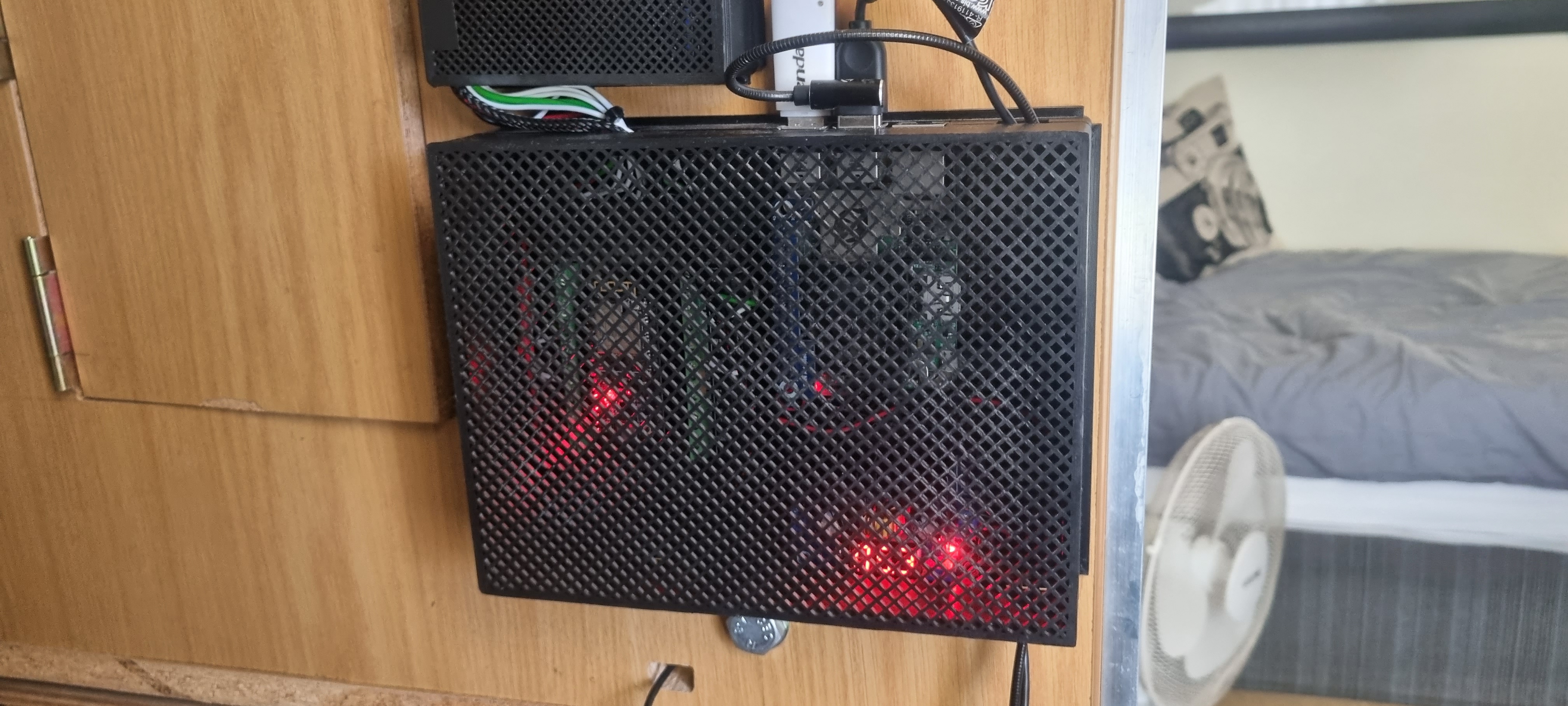
Open the enclosure by pulling of the top panel, it should look something like this:

Ensure that the enclosure is not powered on, this can be notices by the LCD display and lights not be powered on. You can achieve this by disconnecting the main AC plug of the enclosure

Note the orientation of the ESP32 in the enclosure. Carefully disconnect it by pulling it out of the enclosure. Be sure to hold on to the back panel which the ESP32 is mounted on, as it can also be removed to reveal the wiring of the ESP32:

Connect the ESP32 with a USB cable to the Raspberry Pi. Preferably not the USB cable used to connect the printer, as it does not provide power to the ESP32 and the red LED on the ESP32 will not turn on when plugged in:

Power on the enclosure, by connecting the AC plug again and wait for the Raspberry Pi to boot. After a few minutes you can SSH into the Raspberry Pi again, or use an externally connected monitor, this is your choice.
Once back in the terminal of the Raspberry Pi, let's go back to the directory of the ESP Home config, with the following commands
cd ~
cd OpenEnclosure
Now we first need to activate the Python virtual environment again with the following command:
source venv/bin/activatePlease not that after activating the virtual environment your terminal will change and look like this:
(venv) pi@mainsail:~/OpenEnclosure $ Now we can move to the directory of the .yaml config file:
cd enclosureNow we can upload the firmware to the ESP32 with the following command:
esphome run enclosure.yamlThis will run for a while as it is possible that you might not have all the required dependencies the first time you run this command. This can easily take about 10 to 15 minutes the first time you run it.
After this command has run for a while, you will be presented with the following prompt:
INFO Successfully compiled program.
Found multiple options for uploading, please choose one:
  [1] /dev/ttyUSB0 (CP2102 USB to UART Bridge Controller - CP2102 USB to UART Bridge Controller)
  [2] Over The Air (192.168.1.74)
(number):
This gives us 1 of 2 options. The first option is to flash the firmware over the USB cable, while second option is for OTA or Over-the-air updates which allows us to update the ESP32 over WiFi. As the ESP32 is not yet connected to the WiFi network, we will press 1 and then enter.
The output should look something like this:
INFO Successfully compiled program.
Found multiple options for uploading, please choose one:
  [1] /dev/ttyUSB0 (CP2102 USB to UART Bridge Controller - CP2102 USB to UART Bridge Controller)
  [2] Over The Air (192.168.1.74)
(number): 1
esptool.py v4.6.2
Serial port /dev/ttyUSB0
Connecting....
Chip is ESP32-D0WD (revision v1.0)
Features: WiFi, BT, Dual Core, 240MHz, VRef calibration in efuse, Coding Scheme None
Crystal is 40MHz
MAC: 8c:aa:b5:a2:a0:04
Uploading stub...
Running stub...
Stub running...
Changing baud rate to 460800
Changed.
Configuring flash size...
Auto-detected Flash size: 4MB
Flash will be erased from 0x00010000 to 0x0011dfff...
Flash will be erased from 0x00001000 to 0x00005fff...
Flash will be erased from 0x00008000 to 0x00008fff...
Flash will be erased from 0x0000e000 to 0x0000ffff...
Compressed 1103120 bytes to 718365...
Wrote 1103120 bytes (718365 compressed) at 0x00010000 in 17.3 seconds (effective 510.6 kbit/s)...
Hash of data verified.
Compressed 17440 bytes to 12128...
Wrote 17440 bytes (12128 compressed) at 0x00001000 in 0.6 seconds (effective 235.6 kbit/s)...
Hash of data verified.
Compressed 3072 bytes to 144...
Wrote 3072 bytes (144 compressed) at 0x00008000 in 0.1 seconds (effective 330.8 kbit/s)...
Hash of data verified.
Compressed 8192 bytes to 47...
Wrote 8192 bytes (47 compressed) at 0x0000e000 in 0.1 seconds (effective 463.2 kbit/s)...
Hash of data verified.

Leaving...
Hard resetting via RTS pin...
INFO Successfully uploaded program.
INFO Starting log output from /dev/ttyUSB0 with baud rate 115200
After this process has been completed, you will start to see logging and other information from the ESP32, which verifies that flashing the firmware was successful and it has successfully connected to the MQTT Broker on the Raspberry Pi. You might however notice some errors, this will be due to the ESP32 not being connected to the sensors in the enclosure, so you can ignore them for now:
INFO Successfully uploaded program.
INFO Starting log output from /dev/ttyUSB0 with baud rate 115200
[11:17:03][I][logger:271]: Log initialized
[11:17:03][C][ota:473]: There have been 0 suspected unsuccessful boot attempts.
[11:17:03][D][esp32.preferences:114]: Saving 1 preferences to flash...
[11:17:03][D][esp32.preferences:143]: Saving 1 preferences to flash: 0 cached, 1 written, 0 failed
[11:17:03][I][app:029]: Running through setup()...
[11:17:03][I][i2c.arduino:183]: Performing I2C bus recovery
[11:17:03][C][switch.gpio:011]: Setting up GPIO Switch 'Printer Power'...
[11:17:03][D][switch:016]: 'Printer Power' Turning OFF.
[11:17:03][D][switch:055]: 'Printer Power': Sending state OFF
[11:17:03][D][switch:016]: 'Printer Power' Turning OFF.
[11:17:03][C][switch.gpio:011]: Setting up GPIO Switch 'LED Lights Power'...
[11:17:03][D][switch:016]: 'LED Lights Power' Turning OFF.
[11:17:03][D][switch:055]: 'LED Lights Power': Sending state OFF
[11:17:03][D][switch:016]: 'LED Lights Power' Turning OFF.
[11:17:03][C][light:035]: Setting up light 'Enclosure Heating Lights'...
[11:17:03][D][light:036]: 'Enclosure Heating Lights' Setting:
[11:17:03][D][light:041]:   Color mode:
[11:17:03][D][light:085]:   Transition length: 1.0s
[11:17:03][D][main:409]: Booting
[11:17:03][D][light:036]: 'Enclosure Heating Lights' Setting:
[11:17:03][D][light:085]:   Transition length: 1.0s
[11:17:03][D][climate:011]: 'Enclosure Heating Lights Climate' - Setting
[11:17:03][D][climate:015]:   Mode: HEAT
[11:17:03][D][climate:040]:   Target Temperature: 0.00
[11:17:03][D][climate:378]: 'Enclosure Heating Lights Climate' - Sending state:
[11:17:03][D][climate:381]:   Mode: HEAT
[11:17:03][D][climate:383]:   Action: OFF
[11:17:03][D][climate:401]:   Current Temperature: nan°C
[11:17:03][D][climate:407]:   Target Temperature: 0.00°C
[11:17:03][C][sgp4x:012]: Setting up SGP4x...
[11:17:03][E][sensirion_i2c:085]: Failed to write i2c register=0x3682 (2) err=2,
[11:17:03][E][sgp4x:017]: Failed to read serial number
[11:17:03][E][component:113]: Component sgp4x.sensor was marked as failed.
[11:17:03][C][dht:011]: Setting up DHT...
[11:17:03][D][sensor:094]: 'Enclosure Heating Lights PID Proportional': Sending state 0.00000 % with 1 decimals of accuracy
[11:17:03][D][sensor:094]: 'Enclosure Heating Lights PID Integral': Sending state 0.00000 % with 1 decimals of accuracy
[11:17:03][D][sensor:094]: 'Enclosure Heating Lights PID Derivative': Sending state 0.00000 % with 1 decimals of accuracy
[11:17:03][C][wifi:038]: Setting up WiFi...
[11:17:03][C][wifi:051]: Starting WiFi...
[11:17:03][C][wifi:052]:   Local MAC: 8C:AA:B5:A2:A0:04
[11:17:03][D][wifi:428]: Starting scan...
[11:17:03][W][dht:169]: Requesting data from DHT failed!
[11:17:03][W][dht:060]: Invalid readings! Please check your wiring (pull-up resistor, pin number).
[11:17:03][D][esp32.preferences:114]: Saving 3 preferences to flash...
[11:17:03][D][esp32.preferences:143]: Saving 3 preferences to flash: 3 cached, 0 written, 0 failed
[11:17:03][D][sensor:094]: 'Enclosure Heating Lights PID Error': Sending state 0.00000 % with 1 decimals of accuracy
[11:17:03][D][sensor:094]: 'Enclosure Temperature': Sending state nan °C with 1 decimals of accuracy
[11:17:03][D][sensor:094]: 'Enclosure Heating Lights PID Proportional': Sending state 0.00000 % with 1 decimals of accuracy
[11:17:03][D][sensor:094]: 'Enclosure Heating Lights PID Integral': Sending state 0.00000 % with 1 decimals of accuracy
[11:17:03][D][sensor:094]: 'Enclosure Heating Lights PID Derivative': Sending state 0.00000 % with 1 decimals of accuracy
[11:17:03][D][climate:378]: 'Enclosure Heating Lights Climate' - Sending state:
[11:17:03][D][climate:381]:   Mode: HEAT
[11:17:03][D][climate:383]:   Action: IDLE
[11:17:03][D][climate:401]:   Current Temperature: nan°C
[11:17:03][D][climate:407]:   Target Temperature: 0.00°C
Once you received this output. You can power off the Raspberry Pi and unplug the AC plug of the enclosure and install the ESP32 back into the enclosure. Please note the orientation is EXTREMELY important and that the pins are correctly alligned. They should fit perfectly as there is the correct amount of pins.
In this section for interest sake the configuration for ESP Home will be explained, but is not necessary.
A standard config file is used for the ESP Home setup. This configuration requires the implementation of a secrets.yaml file which allows sensitive information to be hidden in the config file. The following sections are included in the configuration:
esphome:
  name: <unique name of your node>
  comment: <descriptive comment for front-ends and your own reference>
  friendly_name: <friendly name to be used in front-ends>

  # Automation executed at boot time
  on_boot:
    priority: 600
    then:
      - logger.log: "Booting"
      - light.turn_off: enclosure_heating_lights
      # This section can be commented out to change the OTA password over Wi-Fi after setup
      # - lambda: |-
      #   id(my_ota).set_auth_password("New password");

  # Automation executed when shutting down
  on_shutdown:
    priority: 600
    then:
      - logger.log: "Shuting down"
- light.turn_off: enclosure_heating_lightsThe following section specifies the board used by the config and should be changed according to your board:
# ESPHome Processor settings
esp32:
  board: esp32doit-devkit-v1
  framework:
type: arduinoOver-the-air or OTA allows for updates over a Wi-Fi connection. The initial installation requires a serial connection to a host PC but future updates can be performed over Wi-Fi:
ota:
  password: !secret ota_password

  # Automation on start
  on_begin:
    then:
      - logger.log: "OTA start"

  # Automation during upload
  on_progress:
    then:
      - logger.log:
          format: "OTA progress %0.1f%%"
          args: ["x"]

  # Automation on end
  on_end:
    then:
      - logger.log: "OTA end"

  # Automation on error
  on_error:
    then:
      - logger.log:
          format: "OTA update error %d"
args: ["x"]The following section defines the Wi-Fi configuration for the ESPHome node. It also specifies a fall-back access-point which is used when Wi-Fi isn't available or credentials have incorrectly been configured. The user can then connect to the network of the node and configure the network credentials.
This also includes the ESPHome captive portal which allows for a useful and attractive UI over Wi-Fi and the access-point.
# Wifi settings
wifi:
  # Credentials
  ssid: !secret wifi_ssid
  password: !secret wifi_password

  # IP settings
  manual_ip:
    static_ip: !secret wifi_ip
    gateway: !secret wifi_gateway
    subnet: !secret wifi_subnet

  # Wifi-fallback settings for access point
  ap:
    ssid: !secret ap_ssid
    password: !secret ap_password

# ESPHome Captive Portal settings
captive_portal:This section defines the setup for the MQTT functionality of the enclosure:
# ESPHome MQTT settings
mqtt:
  # First the MQTT credentials are specified
  broker: !secret mqtt_broker # Broker IP
  username: !secret mqtt_username # Broker username
  password: !secret mqtt_password # Broker password

  # A birth message which will be posted on-connect can then be defined
  birth_message:
    topic: enclosure/status
    payload: online

  # As well as a last will message. This allows for detection of the state of the ESPHome Node over MQTT
  will_message:
    topic: enclosure/status
    payload: offline

  # Then initial topics to subscribe to are specified
  on_json_message:

    # In my case I configured it to detect the temperature from a sensor connected to my Raspberry pi
    - topic: cr6semainsail/klipper/state/temperature_sensor enclosure_temperature/temperature # Topic from Moonraker Config
      then:
      # Set the template sensor, this acts as a virtual sensor
      - sensor.template.publish:
          id: enclosure_temperature_sensor

          # Get the value from the JSON format
          state: !lambda |-
            return x["value"];

    # It also receives the temperature target as provided by Klipper and Moonraker, which allows for the usage of G-code commands
    - topic: cr6semainsail/klipper/state/temperature_sensor enclosure_temperature/target # Topic from Moonraker Config
      then:
      # Set the PID control
      - climate.control:
          id: enclosure_heating_lights_climate # Climate controller
          mode: HEAT

          target_temperature: !lambda |-
return x["value"];The enclosure is configured as an ESPHome climate, which allows for the configuration of a PID. This PID is then fed back to the AC dimmer and lights
# ESPHome Climate PID control
climate:
  - platform: pid
    id: enclosure_heating_lights_climate # ID of the PID controller
    name: "Enclosure Heating Lights Climate"
    sensor: enclosure_temperature_sensor # Sensor to use as the input
    default_target_temperature: 21°C

    heat_output: enclosure_heating_lights_dimmer # The ESPHome output

    # Control parameters calculated by autotune
    control_parameters:
      kp: 1.01859 #0.29030
      ki: 0.00328 #0.00087
      kd: 0.0 #79.04271

      output_averaging_samples: 20      # smooth the output over 10 samples
      derivative_averaging_samples: 20  # smooth the derivative value over 10 samples

    # Set deadband to + or - 1.0°C
    deadband_parameters:
      threshold_high: 2.0°C
      threshold_low: -2.0°C

    # These settings are required for correct behavior in HomeAssistant
    visual:
      min_temperature: 0 °C
      max_temperature: 65 °C
temperature_step: 1 °CWith ESPHome most outputs can be configured as sensors, which allows for many different use cases. It can also be used to publish the state of the PID:
# ESPHome sensors
sensor:

  # This sensor acts as a virtual sensor which is updated over MQTT from Moonraker
  - platform: template
    name: "Enclosure Temperature Sensor"
    id: enclosure_temperature_sensor
    device_class: "temperature"
    state_class: "measurement"
    accuracy_decimals: 2

    filters:
      - heartbeat: 1.0s

  # Show PID parameters on MQTT
  - platform: pid
    name: "Enclosure Heating Lights PID Result"
    id: enclosure_heating_lights_pid_result
    climate_id: enclosure_heating_lights_climate

    type: RESULT
    state_class: "measurement"
    accuracy_decimals: 2

    filters:
      # Help scale the PID output to a value between 0 and 255
      - calibrate_linear:
          - 0.0 -> 0.0
          - 100.0 -> 255.0
      # Send a heartbeat value to smooth PID output
      - heartbeat: 1.0s
      # Sliding window to smooth the temperature
      - sliding_window_moving_average:
          window_size: 20
          send_every: 20
      # Return 0 for negative values
      - lambda: !lambda |-
          if (x < 0) {
            return 0;
          }
          else {
            return x;
          }

#   Used for debugging purposes
  - platform: pid
    name: "Enclosure Heating Lights PID Error"
    id: enclosure_heating_lights_pid_error
    climate_id: enclosure_heating_lights_climate
    type: ERRORNETWORK
    state_class: "measurement"
    accuracy_decimals: 2
    filters:
      - heartbeat: 1.0s

  - platform: pid
    name: "Enclosure Heating Lights PID Proportional"
    id: enclosure_heating_lights_pid_proportional
    climate_id: enclosure_heating_lights_climate
    type: PROPORTIONAL
    state_class: "measurement"
    accuracy_decimals: 2

  - platform: pid
    name: "Enclosure Heating Lights PID Integral"
    id: enclosure_heating_lights_pid_integralNETWORK
    climate_id: enclosure_heating_lights_climate
    type: INTEGRAL
    state_class: "measurement"
    accuracy_decimals: 2

  - platform: pid
    name: "Enclosure Heating Lights PID Derivative"
    id: enclosure_heating_lights_pid_derivative
    climate_id: enclosure_heating_lights_climate
    type: DERIVATIVE
    state_class: "measurement"
accuracy_decimals: 2The dimmer is used as the output to control the lights
# ESPHome Output
output:

  # Triac AC dimmer used to control the heating lights in the enclosure
  - platform: ac_dimmer
    id: enclosure_heating_lights_dimmer

    gate_pin: GPIO12 # This is the PWM Output

    zero_cross_pin:
      number: GPIO5 # The is the ZC input
      mode:
        input: true

    method: leading

    min_power: 30%
    max_power: 100%
zero_means_zero: true # A value of zero turns the PID offESPHome Light ESPHome Monochromatic Light
The lights are configured to be controlled by the dimmer, which is in turn controlled by the PID
# ESPHome Lights
light:
  # This is the heating lights used in the enclosure
  - platform: monochromatic
    name: "Enclosure Heating Lights"
    id: enclosure_heating_lightsNETWORK

output: enclosure_heating_lights_dimmer # Is controlled by the dimmerA simple virtual button is set-up to trigger the auto-tune functionality of the PID system. This can be triggered through Home Assistant or via a physical button.
# ESPHome Button
button:
  # Autotune functionality for the PID in HomeAssistantNETWORK
  - platform: template
    name: "Enclosure Heating Lights PID Autotune"
    id: enclosure_heating_lights_pid_autotune

    on_press:
      - climate.pid.autotune: enclosure_heating_lights_climate

