Comments (10)
 Cleric-K
commented on May 30, 2024
Cleric-K
commented on May 30, 2024
Hi,
it is strange that this happens. The serial port of the arduino is pretty much independent of whatever the receiver is doing. Can we perform several tests?
-
When this disconnect happens does the Windows "USB plugged/unplugged sound sounds"?
-
What happens if you first turn on the transmitter (the receiver should stop blinking) and then try to connect vjsf?
-
To figure out if the problem is in vjsf or with the port in general you can download PuTTY. You can download the installer or simply the .exe from "Alternative binary files/ putty.exe" section.
Open it and make these settings:
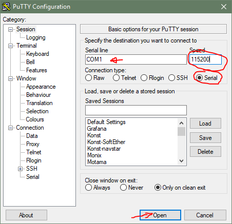
Of course you'll have to type in the correct COM port in your case.
Then after the port is open try again turning on the transmitter and see if the port gets disconnected. If it does - then we are dealing with actual drop out of the arduino's USB serial and not a bug in vjsf. -
Double check your connections. The IBUS of the receiver should go to the TX pin of the arduino and a blank sketch should be uploaded.
Normally, UART tx pins stay in "high" +5V state. If the Arduino is not flashed with blank program and its configured as serial port, it will be in +5V state. When powering up the X6B and there is no connection to a transmitter, initially the X6B does not output anything on its IBUS pin - thus it stays in +5V. When this is connected to the TX pin - both are outputting +5V and there is no problem. But at the moment it tries to output anything - it sends the first start bit which is 0V and you have +5V connected directly to 0V - which is short circuit and usually will burn out the pins. At the same time the whole current flows through this short circuit leaving almost no current for the remaining electronics which effectively powers them down. This is one possible explanation why the serial port flaps.
You can try to measure the arduino TX pin voltage (without the IBUS) to see if it show anything. If it is properly set as input there shouldn't be any voltage present (that is - there should be no difference if you are touching the pin with the probe or not). If it shows +5V or something like that it could be the source of the problem.
from vjoyserialfeeder.
 F-Amaral
commented on May 30, 2024
F-Amaral
commented on May 30, 2024
Hello, thanks for the reply.
About the test results:
1 - Windows does makes the disconnecting sounds, and I can no longer access the arduino COM port.
2 - I'm not sure how to test this, since I'm feeding 5V from the usb via arduino to the receiver, and it disconnects as soon as I turn the controller on. the receiver stays on, just seems like it loses the hability to send data over the TX pin
3 - I tried with PuTTY and got the same results, disconnecting when I turn the controller on. Which I guess makes this a non SerialFeeder issue.
4 - Well, this seems to be an issue, although I've cleared the Arduino EEPROM several times, I'm getting 4.46V between TX and Ground. Any suggestions on how to fix this?
from vjoyserialfeeder.
Cleric-K
commented on May 30, 2024
Ok. So either the pin has been damaged or for some reason it is set in Output mode (which is strange because when you flash blank sketch all pins are Inputs by default).
You can try flashing a blank sketch with only modifying setup() as:
void setup() {
  pinMode(1, INPUT);
}
Pin 1 should be TX on the UNO I think. Please double check the labels on the board. The above code should put the pin in Input mode which is high impedance mode (as if not connected to anything), so measuring the voltage at it should not give anything.
If you still measure voltage at it, most probably there's some damage. Either the port is stuck in Output mode or it is not working at all.
If you want to find out if it is working you can flash some sketch that writes to the serial port (data going out of TX) - for example File/Examples/01.Basics/DigitalReadSerial. When you open Tools/Serial Monitor (baud rate should be 9600) you should see numbers dumping. If not - it means that the pin is completely damaged.
from vjoyserialfeeder.
Cleric-K
commented on May 30, 2024
Actually I might be wrong about the voltage on the TX port. I did some tests now and it really reads 5V. I think the reason could be because the TX and RX pins are actually connected on the arduino to the UART USB chip, so measuring the TX when it is in high impedance mode actually measures the voltage at the UART chip.
Turns out the voltage will not be a reliable test.
You can still try the Input pin mode and the serial dump example to make sure everything is working.
Then you can try to flash the Input mode sketch and use a jumper wire to manually connect GND with TX (just touch for a moment) and see if the boards resets again.
from vjoyserialfeeder.
F-Amaral
commented on May 30, 2024
Okay, so I've done everything above. The serial test runs ok, printing a lot of 0 in the console, briefly shorting tx to gnd doesn't reset the board, and whenever the receiver is in binding mode, the TX light flashes like crazy. As soon as I turn on the controller, the arduino disconnects and the TX light go off.
Also, for peace of mind, I've tried connecting a 10 Ohm resistor in series with the TX pin.
None of those seemed to fix the issue, I'm really lost on what could be happening.
from vjoyserialfeeder.
Cleric-K
commented on May 30, 2024
That's really strange indeed.
I'm not too versed in electronics so at this point I'm also at loss. The only other thing to test I can think of is to power the rx from somewhere else and only keep the grounds connected and tx. Maybe the rx draws too much current after connect...I really have no clue.
I'll see if I'll dream of a solution this night :)
from vjoyserialfeeder.
F-Amaral
commented on May 30, 2024
Okay, so I've actually supplied 5V from a usb wall adapter to my receiver, and it worked. I've connected the adapter ground to the arduino ground, and uploaded the sketch only setting pin 1 as input.
So I guess this stay as a tip for the documentation page.
I cannot thank you Cleric-K enough for all the help, especially because the issue wasn't with your software, but with my setup. Now everything is working fine. Cheers!
from vjoyserialfeeder.
Cleric-K
commented on May 30, 2024
Well, I'm glad it worked out... although in not very satisfying way. Having to supply external power takes away from the elegance of the solution.
I have x6b, ia6b and fs82 receivers and never had issues like that so it may be some faulty electronics either at the rx or the arduino.
Do you have some other uart converter to test with? Another arduino, or better still - ftdi adapter or uart usb cable?
Another thing that can be tested could be to experiment connecting the arduino to other usb ports on the pc. Some ports provide lower power ratings than other, although I don't think this can be the issue. This usually affects high power devices like external hard drives, but the consumption of the arduino+receiver should be quite small anyway.
Another thing which might be tested would be to connect some higher value capacitor between the ground and +5v. Maybe this will provide some further stability and avoid voltage spikes/drops if this is the cause of the problem.
Btw if you are using flysky products you might be interested in another project I've uploaded: https://github.com/Cleric-K/FlySkyRxFirmwareRssiMod. It is a custom firmware for some flysky receivers which sends RSSI % on IBUS channel 14.
from vjoyserialfeeder.
F-Amaral
commented on May 30, 2024
Well, this solution really isn't optimal, and I do agree we could try and find a better one.
I have tried multiple USB ports, both 2.0 and 3.0 with no luck.
I don't have an ftdi adapter yet, but I will buy one and report the test results later.
Also, a friend of mine have another arduino I can experiment with, and so I shall also test it.
I've never had an issue with my current arduino, and the only other uart converter I have at hand now is a DB9 to USB using a ch340, but it's only set to work with 3V, so I will have to mod it to supply the full 5V.
Now, enginerding time:
I've tested a 330uF eletrolytic cap, it did stabilize it enough to keep the connection alive and working.
Measuring the voltage between +5V and GND on the arduino is supplying 4.6V, which should be enough to power the receiver. However, the sensored data I get on my controller from the RX is only 4.3V which already makes it beep alerting for low battery voltage.
This difference made me somewhat suspicious, and directly measuring the AMS1117 output confirms it is only outputting 4.3V. Which means I probably have a defective adjusting resistor connected to the regulator.
For now, the capacitor solves the issue, but I will dig deeper into the regulating problem, and try to replace the resistor.
I cannot thank you enough for all the help, and if you need any more tests, I will be happy to perform them.
Cheers!
from vjoyserialfeeder.
Cleric-K
commented on May 30, 2024
Hi,
sorry for the delayed reply.
I don't know if you already did some more tests. I just wanted to add that the problem is probably not with the regulator because I think it is only used when you power the board with external voltage 9-12V (or the Vin pin).
I was looking at the schematics and it seems that the presence of Vin voltage commands the FDN340P transistor switch. If there is no outer power the transistor should bridge the USB 5 volt (USBVCC) to the Arduino +5V rail.
So with this in mind the only thing I can think of testing is to see how different is the USBVCC from the +5V rail - in other words what is the voltage across the Source and Drain of the mosfet. It would be interesting to see if this is where the voltage is dropped (there will be always some voltage across it, but I'm not sure how much is normal) , or USBVCC itself drops.
It might also be the case that the problem is with the receiver itself. For some reason it may be using abnormally high current when transmitting. Just guessing.
Good luck!
from vjoyserialfeeder.
Related Issues (20)
- How to decipher Channels HOT 25
- No joystick to choose HOT 1
- XK X8 Help HOT 4
- Help with Custom Controller Protocol HOT 9
- Facing Connected failsafe serial port read timeout error HOT 4
- Connecting İbus Receiver HOT 2
- not reading serial data HOT 6
- I don't know my problem, there's two of them. HOT 8
- l HOT 21
- Readable map of buttons -> joy pad button HOT 1
- dji rc N1 HOT 6
- Rotatory encoder implementation HOT 3
- vjoy Connected,Failsafe(waiting for serial data) HOT 31
- how to add buttons with your old joystck in vjoy HOT 7
- SERaero serial protocol implementation
- Disappearing port HOT 4
- Raspberry Pi Pico IBUS - Failsafe (Serial Port Read Timeout) HOT 6
- Radiolink T8FB BT usb com not visible in vjoyserialfeeder HOT 10
- Potentiometer value keep changing slightly HOT 1
- vJoySerialFeeder with SBUS is glitching HOT 10
Recommend Projects
-
 React
React
A declarative, efficient, and flexible JavaScript library for building user interfaces.
-
Vue.js
🖖 Vue.js is a progressive, incrementally-adoptable JavaScript framework for building UI on the web.
-
 Typescript
TypeScript is a superset of JavaScript that compiles to clean JavaScript output.
-
TensorFlow
An Open Source Machine Learning Framework for Everyone
-
Django
The Web framework for perfectionists with deadlines.
-
 Laravel
A PHP framework for web artisans
-
D3
Bring data to life with SVG, Canvas and HTML. 📊📈🎉
-
Recommend Topics
-
javascript
JavaScript (JS) is a lightweight interpreted programming language with first-class functions.
-
web
Some thing interesting about web. New door for the world.
-
server
A server is a program made to process requests and deliver data to clients.
-
Machine learning
Machine learning is a way of modeling and interpreting data that allows a piece of software to respond intelligently.
-
Visualization
Some thing interesting about visualization, use data art
-
Game
Some thing interesting about game, make everyone happy.
Recommend Org
-
Facebook
We are working to build community through open source technology. NB: members must have two-factor auth.
-
Microsoft
Open source projects and samples from Microsoft.
-
Google
Google ❤️ Open Source for everyone.
-
Alibaba
Alibaba Open Source for everyone
-
D3
Data-Driven Documents codes.
-
Tencent
China tencent open source team.
from vjoyserialfeeder.